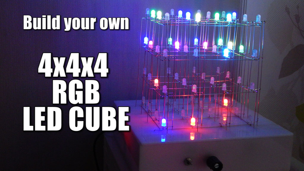
Summary of Build your own 4x4x4 RGB LED Cube using arduino
This article guides the construction of a 4x4x4 RGB LED Cube with a focus on creating the cube, assembling the case, and then building the electronic controller using Arduino and other components. It provides video tutorials and detailed parts lists available from eBay, Amazon.de, and Amazon.com. The project combines soldering skills and basic electronics to create a colorful and visually impressive LED display.
Parts used in the 4x4x4 RGB LED Cube:
- RGB LEDs Common Anode
- Silvered Copper Wire (Bridge Wire)
- Solder
- Ribbon Cable
- DC Jack
- Switch
- Potentiometer (10k)
- Arduino Nano
- TLC5940 LED driver
- Resistor Kit
- Power Supply (5V, 2A)
- IRF9540N P-Channel MOSFET
- Capacitor Kit
- Prototyping PCB
LED Cubes are awesome. The first one I created was a 8x8x8 blue led cube. It still works like a charm. But being able to display every colour in the spectrum is much more spectacular. Let’s start with a small and simple 4x4x4 RGB LED Cube.
Step 1: Watch part 1 of the video series!
As you might have noticed, part 1 concentrates on the cube itself and the case. No electronics yet. The video should already give you plenty of details. But I will give you a short list of parts that you will need to build the cube itself.
Step 2: Order the parts for the cube!
Ebay:
RGB LEDs Common Anode: http://rover.ebay.com/rover/1/711-53200-19255-0/1?…
Silvered Copper Wire (Bridge Wire):http://rover.ebay.com/rover/1/711-53200-19255-0/1?…
Solder: http://rover.ebay.com/rover/1/711-53200-19255-0/1?…
Ribbon Cable: http://rover.ebay.com/rover/1/711-53200-19255-0/1?…
Amazon.de:
RGB LEDs Common Anode: http://amzn.to/1cjetjZ
Silvered Copper Wire (Bridge Wire): http://amzn.to/1cjeHaH
Solder: http://amzn.to/1lHSJ48
Ribbon Cable: http://amzn.to/1m8P3JA
Amazon.com:
RGB LEDs Common Anode: http://amzn.to/1vwIcu9
http://amzn.to/1nU75Sf
Silvered Copper Wire (Bridge Wire): http://amzn.to/ZcMqwN
Solder: http://amzn.to/1nU7dkE
Ribbon Cable: http://amzn.to/1nU7fsD
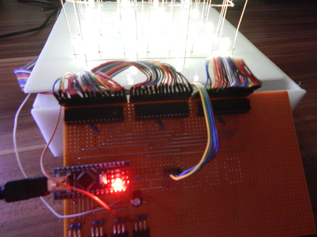
Step 3: You finished the cube and case!
Congrats on your finished cube and case. It should now look a little bit like mine in the picture. Go ahead and test all connections with a power supply. If everything works fine you can go ahead and build the electronics in the next steps.
Step 4: Watch part 2 of the video series!
The video gives you plenty of info on how to build the controller for the cube. In the next step I will give you the schematic for the circuit and the part list.
Step 5: Order the parts for the controller and solder it!
Ebay:
DC Jack:http://rover.ebay.com/rover/1/711-53200-19255-0/1?…
Switch: http://rover.ebay.com/rover/1/711-53200-19255-0/1?…
Potentiometer (10k):http://rover.ebay.com/rover/1/711-53200-19255-0/1?…
Arduino Nano: http://rover.ebay.com/rover/1/711-53200-19255-0/1?…
TLC5940: http://rover.ebay.com/rover/1/711-53200-19255-0/1?…
Resistor Kit:http://rover.ebay.com/rover/1/711-53200-19255-0/1?…
Power Supply (5V, 2A): http://rover.ebay.com/rover/1/711-53200-19255-0/1?…
IRF9540N P-Channel MOSFET:http://rover.ebay.com/rover/1/711-53200-19255-0/1?…
Capacitor Kit:http://rover.ebay.com/rover/1/711-53200-19255-0/1?…
Prototyping PCB: http://rover.ebay.com/rover/1/711-53200-19255-0/1?…
Amazon.de:
DC Jack: http://amzn.to/1Ed1hrt
Switch: http://amzn.to/1vi1UsA
Potentiometer (10k): http://amzn.to/1nRws1J
Arduino Nano: http://amzn.to/1d4H1w1
TLC5940: http://amzn.to/1rVmQZC
Resistor Kit: http://amzn.to/1gt9XPf
Power Supply (5V, 2A): http://amzn.to/1rUJuQN
Capacitor Kit: http://amzn.to/1yE71u3
Prototyping PCB: http://amzn.to/1rVpcI9
Amazon.com:
DC Jack: http://amzn.to/1vBQHEL
Switch: http://amzn.to/1nU8jwB
Potentiometer (10k): http://amzn.to/1Ed2MGb
Arduino Nano: http://amzn.to/1nU8pEE
TLC5940: http://amzn.to/1vwNnKw
Resistor Kit: http://amzn.to/1CJXHUf
Power Supply (5V, 2A): http://amzn.to/1x9Je0G
Capacitor Kit: http://amzn.to/Z0KcQP
Prototyping PCB: http://amzn.to/1rUMJb0
For more detail: Build your own 4x4x4 RGB LED Cube using arduino