
Summary of Brute force attack a BIOS with Arduino
This article describes a proof-of-concept project using an Arduino to emulate a USB keyboard and sniff VGA signals to brute-force a BIOS password. The system sends repeated password attempts while monitoring a specific screen pixel's color to determine if the entry was correct or incorrect. Due to the slow nature of the brute-force method and hardware limitations like not reading full VGA frames, this is intended for educational purposes only.
Parts used in the Brute force attack a BIOS with Arduino:
- Arduino board
- V-USB library for Arduino
- LCD module
- Zener diodes
- Button (for pause/reset)
The goal of this experiment is to convert the Arduino board into an USB keyboard plus a VGA sniffer to crack the password of a standard BIOS using the brute force attack method. There are no advantages in using this method, in fact this can be very slow and you may never find the password at all, but as always we do it for fun. It’s just a proof of concept, there are many ways of resetting a BIOS specially if you have access to the hardware, and you need it anyway because we’re talking about BIOS and there is no “remote access” as far as I know.
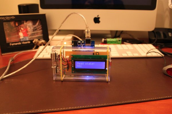
In theory, you can use it with other programs also not only a BIOS setup, but there must be some special conditions, for example the software must be one of those that doesn’t block after a few failed password entry attempts.
Also one of the main limitations is that we cannot read the whole VGA frame and process it, instead we read one single pixel from (more or less) the middle of the screen, and according to its color we go through the different steps, for example: a red pixel in the middle of the screen may indicate that the password is wrong in a regular BIOS setup, while a blue pixel can indicate that it is ready to receive the next password.
USB Keyboard Emulator
For the USB keyboard part, I’ve used the V-USB for Arduino code, which in turns uses V-USB library. You will need to install the V-USB for Arduino to make the “pde” work.
Circuit
The Arduino shield for this project is pretty simple, I’ve attached a regular LCD module to have an output to avoid a second computer just to see the progress or result.
A couple of Zener diodes to make the USB keyboard interface (it’s one of the four options suggested in the V-USB Readme, here is a link to another project that uses this method also).
There is a button which is used to pause/continue the attack. If you keep the button pressed for more than 2 seconds, the attack will be reset.
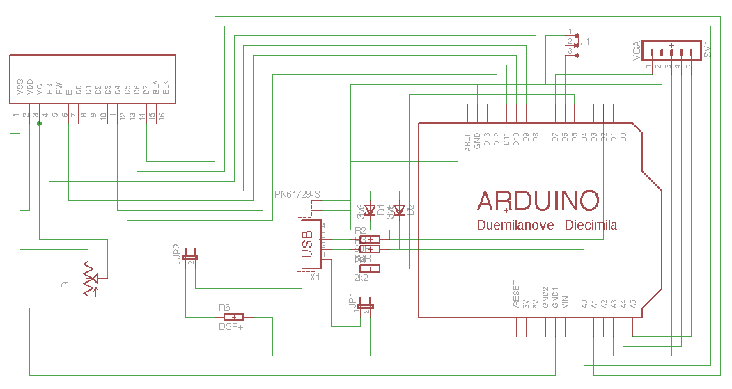
Sniff the VGA
To know the color of the pixel in the middle of the screen, we need to read the analog Red signal, and also the vertical and horizontal synch pulses to know when to read the Red. The first attempt was using Arduino’s attachInterrupt to capture the HSYNC and VSYNC but the overhead made the USB keyboard to stop working.
The ISR() and SIGNAL() macros seems to work better in this case, so the VSYNC pulse will reset a global variable called h_line while the HSYNC will increment it to know in which line is the VGA frame being drawn.
Our waitWrongPassword function does the analysis of the pixel. It waits for a few seconds to appear the red pixel, and keeps looking at the line counter so when it is in the #238 (almost the vertical middle in an 640×480 resolution) it will delay a little bit to get the horizontal middle timing, and read the analog input.
For more detail: Brute force attack a BIOS with Arduino
- What is the goal of this experiment?
The goal is to convert the Arduino board into a USB keyboard plus a VGA sniffer to crack the password of a standard BIOS using the brute force attack method. - Can this method be used remotely?
No, there is no remote access as far as known because you need physical access to the hardware to talk to the BIOS. - How does the system detect if a password is wrong?
A red pixel in the middle of the screen may indicate that the password is wrong in a regular BIOS setup. - Which macro seems to work better for capturing sync pulses?
The ISR() and SIGNAL() macros seem to work better than attachInterrupt to capture HSYNC and VSYNC without stopping the USB keyboard. - At what line counter does the system read the analog input?
The system waits until it is in line #238, which is almost the vertical middle in a 640×480 resolution. - What happens if you keep the button pressed for more than 2 seconds?
If you keep the button pressed for more than 2 seconds, the attack will be reset. - Does the software block after failed password entries?
This method works best with software that does not block after a few failed password entry attempts. - Why is this considered a proof of concept?
It is a proof of concept because the method can be very slow and you may never find the password at all.
