Summary of Automated Arduino Tap
This project is an automatic dog water tap that uses a sensor to detect when the dog approaches and opens a solenoid valve, allowing the dog to drink from a 20L bucket without human assistance. The system prevents the dog from waiting by hours for a tap to be opened manually.
Parts used in the Automatic Dog Water Tap:
- 12V solenoid valve
- Arduino Nano
- HC-SR04 range sensor
- 10K resistor
- Diode
- MOFSET (IRFZ24N)
- 12V battery
- Jumper cables
- Breadboard
- Female spade terminals
- Heatshrink
- 20L bucket
- Twin flex cable
- Epoxy glue
- Plumbing pieces (elbow joints and connectors)
- Strip of flexible metal
- Rivets
- Two small plastic containers
This project was designed for my dog, who refuses to drink from a water bowl. She often sits by the tap for hours waiting for someone to pass and open it for her. So I built her this automatic tap that opens when it senses her and closes again when she’s out of range.
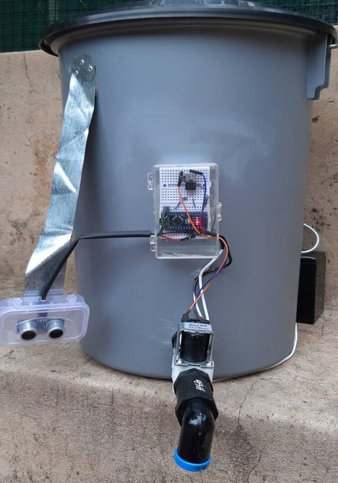
The whole setup is centered around a 20L bucket. This allows it to stand even where there is no tap. It uses a Arduino Nano as a controller, a normally closed solenoid valve as a tap and a 12V battery as a power supply.
I created this tap as a solution to a problem that, while most people probably never experience it, was quite a problem to my family. Trust me, there is nothing sadder than a dog sitting for probably half an hour waiting for someone to see her and open the tap. And then to stand there and wait for her to finish before you can go about your business can also be a nuisance.
Supplies
12V solenoid valve
Arduino nano
HC-SR04 range sensor
10K resistor
Diode
MOFSET (I used a IRFZ24N)
12V battery
Jumper cables
Breadboard
Female spade terminals for the battery and solenoid valve
Heatshrink
A bucket
About a meter of twin flex
Epoxy glue
Some plumbing pieces the same diameter as your solenoid. I used 2 elbow joints and 2 connector pieces
A strip of flexible metal
Some rivets
Two small plastic containers to protect your components from the elements
Step 1: Connecting the Circuit
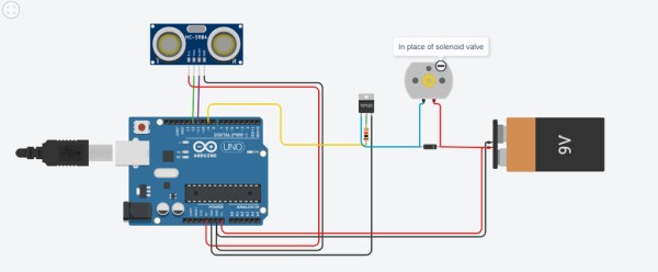
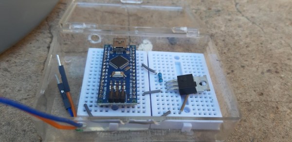
Connect everything together as shown in the schematic above and mount it onto a mini breadboard.
The DC motor in the schematic represents the solenoid.
The reason for the MOFSET is that the Arduino can’t drive the 12V solenoid by itself. The Arduino’s output is only 5V therefore the MOFSET allows the Adruino to still control the solenoid while the battery powers it. The battery also powers the board through the VIN pin.
It isn’t recommended to omit the diode. The solenoid opens and closes by means of an electromagnet. The closing magnetic field can induce a backward flowing current that damages the board.
Step 2: The Code
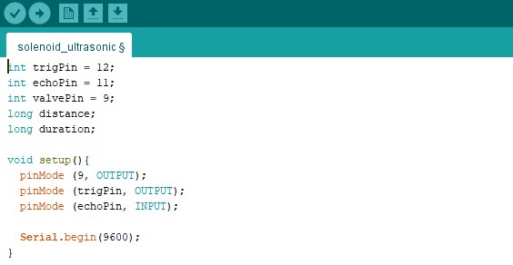
int trigPin = 12;
int echoPin = 11;
int valvePin = 9;
long distance;
long duration;
void setup(){
  pinMode (9, OUTPUT);
  pinMode (trigPin, OUTPUT);
  pinMode (echoPin, INPUT);

  Serial.begin(9600);
}
void loop() {
  ultra();

  if(distance <= 25){
  digitalWrite (9, HIGH);
    Serial.print("Distance: ");
    Serial.println(distance);
  }

  else {
    digitalWrite (9, LOW);
  }

}
void ultra(){ //the range sensor's code
  digitalWrite(trigPin, LOW);
  delayMicroseconds(2);
  digitalWrite(trigPin, HIGH);
  delayMicroseconds(10);
  digitalWrite(trigPin, LOW);
  duration = pulseIn(echoPin, HIGH);
  distance = duration*0.034/2;
  }
Step 3: The Bucket: Part 1
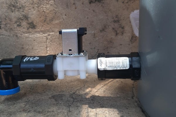
Drill a hole the diameter of your solenoid as close to the bottom of the bucket as possible.
Screw the pieces together as shown, then screw the elbow piece into the rest through the hole.
Step 4: The Bucket: Part 2
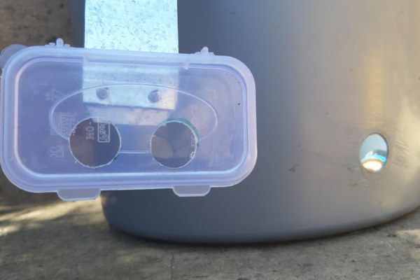
First, mark and drill holes for the range sensor into its container (the sensor box). Drill another hole on the top for the wires to come out.
Next, cut a strip of metal and rivet it onto the top of the bucket. On the other end, rivet the container.
Put the sensor inside. Pull the wires through the holes and connect them.
Step 5: Assembly: Part 1
Drill holes on the sides of the other container (control box). Place the breadboard inside and string the wires through the holes.
Manipulate any components so that they fit into the box.
Step 6: Assembly Part 2
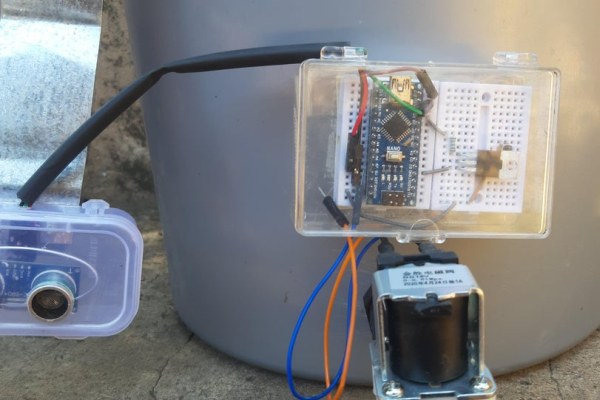
Attach the solenoid’s spade terminals to one end of two male-to-male jumper wires. Run the male ends through the control box’s hole.
Wire the positive terminal of the battery to the VIN pin and the negative to the ground pin.
Source: Automated Arduino Tap
- Why was this automatic tap built?
The project was created because the author's dog refuses to drink from a bowl and waits by the tap for hours. - How does the system power the solenoid valve?
A 12V battery powers the solenoid while the Arduino controls it via a MOFSET since the Arduino only outputs 5V. - What is the purpose of the diode in the circuit?
The diode prevents backward flowing current induced by the closing magnetic field of the electromagnet from damaging the board. - At what distance does the tap open for the dog?
The code sets the trigger point so the valve opens when the sensor detects a distance of 25 or less. - How are the components protected from the elements?
The electronics are housed inside two small plastic containers secured with rivets and epoxy glue. - What acts as the water source reservoir?
A 20L bucket serves as the main container, allowing the setup to stand independently without a fixed tap connection. - Which pins are used for the range sensor on the Arduino?
The trigPin is connected to pin 12 and the echoPin is connected to pin 11. - How is the control box assembled?
Holes are drilled on the sides of a plastic container to mount the breadboard and string wires through them.