Summary of Automated 5 Gallon Bucket Feeder
This project describes an automated cat feeder made from a 5-gallon bucket, designed to dispense dry cat food at programmable intervals using an Arduino Nano controlled stepper motor driving an auger. The feeder can store about 2.5 gallons of food, ideal for weekend feeding or early morning use. It features DIY 3D-printed parts, laser-cut plywood components, and wired electronics, allowing for precise food dispensing controlled via a programmable timer switch.
Parts used in the Automated 5 Gallon Bucket Feeder:
- Arduino Nano
- 12 V laptop power supply
- Programmable outlet timer switch
- Nema 17 stepper motor (64 oz*in or higher)
- L298N stepper motor driver
- Female to female jumper wires (2.54 mm pitch)
- Male to male jumper wires (2.54 mm pitch)
- Male to female jumper wires (2.54 mm pitch)
- 5 gallon bucket with lid
- 1 1/2 inch Schedule 40 PVC tee
- 3/4 inch cable grommet
- M3 8 mm long screws
- M3 12 mm long screws
- M3 lock washers
- M3 nuts
- 4 inch cable ties
- 75 ml tube of silicone sealant
- 100 grit sandpaper sheet
- Thread lock fluid
- 3D printed auger and motor mount parts (made of PLA)
- Laser cut plywood feeder frame and base parts (1/8 inch birch plywood)
This bucket feeder design was motivated by the fact that my wife and I live in different cities and have a cat that hates to ride in the car. The automated feeder makes it possible to be able to leave our cat at one apartment for a weekend without worrying about if she is getting fed or we are leaving too much food out.
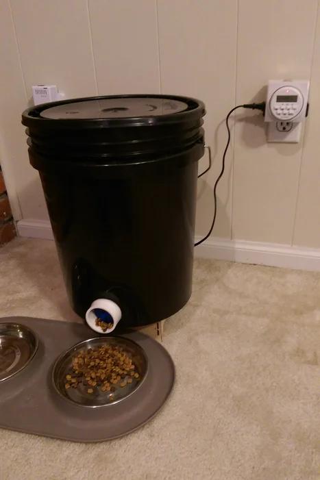
This bucket feeder is also good for everyday feeding. Especially, if your cat annoys you early in the morning until you wake up to feed her like ours does. Just set the programmable timer to energize the feeder at whatever time before you wake up and your cat will at least have less of a reason to come annoy you.
This is generally not cheaper than buying an automated feeder, but it has a larger feed capacity than most that are commercially available. The feed capacity is approximately 2.5 gal (9.5 liter).
The feeder with dispense approximately 1/4 to 1/3 cup of feed for every minute that it is energized. For example, if you want to dispense 3/4 to 1 cup of feed, the timer should be set to energize the feeder for three minutes. The amount dispensed may vary depending on the shape and size of feed used.
This feeder has only been tested with cat food but it probably would work for other types of feed like peanut m&m’s or chicken feed.
It hasn’t been tested outdoors either but if you sealed it up enough I imagine it would work.
Tools required:
- Wire cutter
- Wire stripper
- Small phillups screw driver
- Chordless drill
- 1/8 in drill bit
- 3/4 in hole cutter
- 2 in hole cutter
- Wrasp file
- Utility knife
- 3D printer (60x60x120 mm minimum print volume)
- Laser cutter (24×12 in minimun bed size)
Electronic parts (can be bought on Amazon):
- Qty 1 – Arduino Nano
- Qty 1 – 12 V laptop power supply – https://www.amazon.com/15-e00xxx-15-e002AU-15-e01…
- Qty 1 – Programmable outlet timer switch – https://www.amazon.com/Century-Heavy-Digital-Progr…
- Qty 1 – Nema 17 stepper motor (64 oz*in or higher)
- Qty 1 – L298N stepper motor driver
- Qty 4 – Jumper wire, 2.54 mm pitch, female to female
- Qty 4 – Jumper wire, 2.54 mm pitch, male to male
- Qty 2 – Jumper wire, 2.54 mm pitch, male to female
Hardware store parts:
- Qty 1 – 5 gal bucket with lid
- Qty 1 – 1 1/2 in Sch 40 PVC tee
- Qty 1 – 3/4 in cable grommet
- Qty 2 – M3 8 mm long screw
- Qty 3 – M3 12 mm long screw
- Qty 4 – M3 lock washer
- Qty 3 – M3 nut
- Qty 30 – 4 in cable ties
- Qty 1 – 75 ml tube of silicone sealant
- Qty 1 – 100 grit sand paper sheet
- Qty 1 – thread lock fluid
Step 1: 3D Print the Auger and Motor Mount
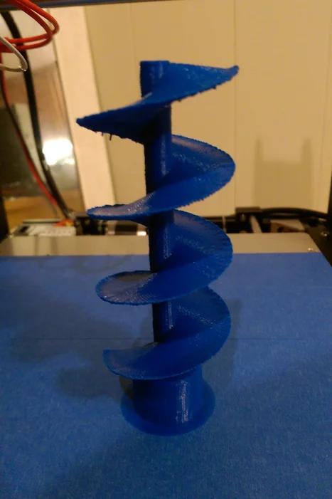
The .STL files to 3D print are included below.
Below are the 3D print settings that I used on my HICTOP prusa i3 to print the auger and motor mount. You may need to tweak the settings to get a good print depending on which 3D printer you are using. The print volume of the 3D printer must be at least 60x60x120 mm.
Auger 3D print settings:
- Material: PLC
- Wall thickness: 1.5 mm
- Infill density: 30%
- No supports
- Must use a brim to ensure that the part is secured to the bed during printing
Motor mount 3D print settings:
- Material: PLC
- Wall thickness: 1.5 mm
- Infill density: 30%
- No supports
Use a utility knife to trim off the brim and clean up the parts.
Don’t have access to a 3D printer? I have had good luck with getting 3D printed parts through 3dhubs.com. Select a local manufacturer, upload the 3D part files, select the material, and you can pick up the parts or have them mailed to you.
Step 2: Laser Cut the Feeder Frame and Base
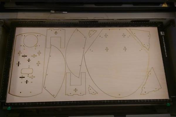
The vector graphics .svg files to laser cut are attached. You will need to laser cut one of each file.
Use two 24 in x 12 in pieces of 1/8″ birch plywood to laser cut the parts.
Don’t have access to a laser cutter? I have had good luck with getting parts laser cut through ponoko.com. Upload the vector files to their site, pick the material, and they will mail the completed parts to you.
Step 3: Assemble the Base
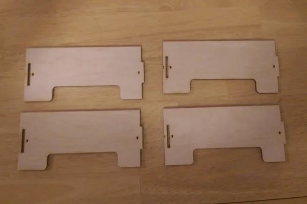
All feeder base parts are held together by 4 in cable ties.
When installing the cable ties, ensure that the cable tie heads are on the inside of the base frame.
Use wire cutters to trim off the extra length of each cable tie.
Step 4: Assemble the Feeder Frame
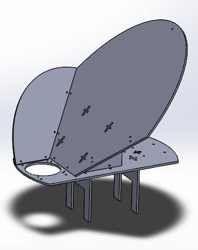
Assemble the feeder frame as shown.
All feeder frame parts are held together by 4 in cable ties.
When installing the cable ties, ensure that the cable tie heads are on the bottom side of the frame.
Use wire cutters to trim off the extra length of each cable tie.
Step 5: Assemble the Auger and Motor Mount
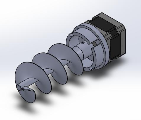
Assemble the motor and auger assembly as shown.
Secure the 3d printed motor mount part to the stepper motor using two M3 8mm screws and two M3 lock washers.
Place the M3 nut into the slot of the auger base. Apply a liberal amount of thread lock fluid to the M3 12mm screw. Use the M3 12 mm screw to secure the auger to the stepper motor shaft.
Use sandpaper to either sand down the auger or PVC tee in order for the auger to turn freely when installed in the tee.
Step 6: Drill Holes in the Bucket
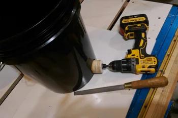
Use the 2 in hole saw to drill the feeder hole in the side of the bucket right at the top surface of the bottom of the inside of the bucket. Use the rasp file to widen the hole so the 1 1/2″ PVC tee will fit when pushed through the hole from the inside of the bucket. Ensure that the PVC tee sits flush with the top of the bottom of the inside of the bucket.
Use the 3/4 in hole saw to drill power chord hole in the side of the bucket directly opposite the 2″ feeder hole. Drill this hole about an inch above the top surface of the bottom of the inside of the bucket.
Step 7: Wire the Electronics
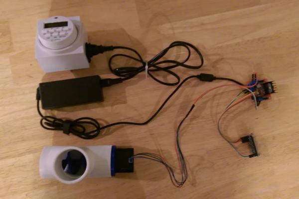
Use wire cutters to cut off the power supply connector. Use wire strippers to strip the power supply wires.
Use the female to female jumpers to connect channels 1, 2, 3, and 4 of the stepper motor driver to 9, 10, 11, and 12 of the Arduino Nano respectively.
Connect the power supply leads to the +12V and GND terminals of the stepper motor driver.
Using the male to male jumpers connect channels A-, A+, B-, and B+ of the stepper driver and to the stepper motor channels per the stepper motor data sheet.
Using the male to female jumpers, connect channels +5V and GND of the stepper motor driver to channels Vin and GND of the Ardunio.
Step 8: Program the Controller
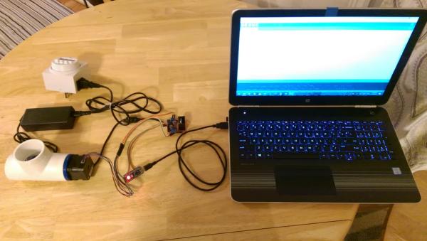
Upload the attached “auto_bucket_feeder” sketch to the Arduino Nano via the Arduino IDE.
Once the sketch has been uploaded, plug in the 12 V power supply into a wall outlet and ensure that the stepper motor is working properly. It should be turning a quarter turn counterclockwise and then an eighth of turn clockwise until it has turned a total of three turns counterclockwise as viewed from the back of the motor. If it is going the opposite direction, just flip the connections between the stepper motor and stepper motor driver.
One of the most important components of this code is that it turns off power to the stepper motor between dispensing intervals. This helps prevent the stepper motor and stepper motor driver from overheating.
/*
Automated Bucket Feeder
This program drives a bipolar stepper motor.
The motor is attached to digital pins 9 – 12 of the Arduino.
The motor will rotate a quarter turn counterclockwise then an eighth turn clockwise until the motor has rotated counterclockwise a total of three turns. This back and forth rotation rattles the feed and ensures that the feed does not clog the auger.
Created 09 Sept. 2017
by John Opsahl
*/
#include
const int stepsPerRevolution = 200; // change this to fit the number of steps per revolution
// for your motor
// initialize the stepper library on pins 9 through 11:
Stepper myStepper(stepsPerRevolution, 9, 10, 11, 12);
void setup() {
// set the speed at 60 rpm:
myStepper.setSpeed(60);
// initialize the serial port:
Serial.begin(9600);
}
void loop(){
for (int i = 0; i < 24; i ++){
//counterclockwise rotation
myStepper.step(-stepsPerRevolution*.25);
//clockwise rotation
myStepper.step(stepsPerRevolution*.125);
}
//turn off power to the stepper motor, to save power and help prevent the stepper motor
//and stepper motor driver from overheating
digitalWrite(8, LOW);
digitalWrite(9, LOW);
digitalWrite(10, LOW);
digitalWrite(11, LOW);
//wait 60 seconds
delay(60000);
}
Step 9: Put It All Together
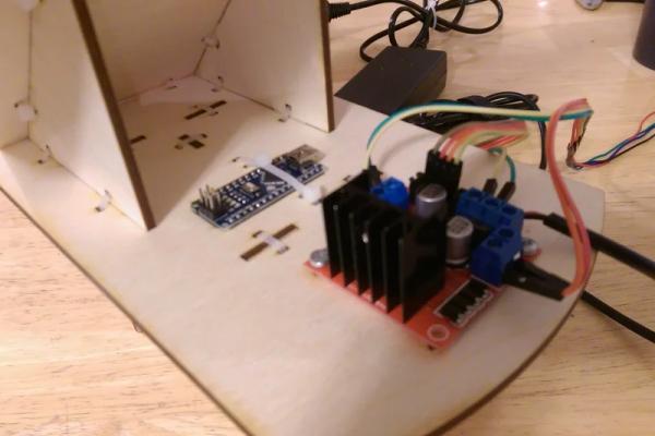
Mount the Arduno Nano and stepper motor driver on the feeder frame as shown. The Arduino Nano is mounted with two zip ties. The stepper motor driver is mounted with two M3 12 mm screws, two M3 lock washers, and two M3 nuts.
Install the 3/4 in cable grommet in the power supply hole that was drilled in the bucket. Push the power supply connection through the grommet.
Set PVC tee, motor, and auger assembly into place at the bottom of the bucket. Orient the motor so two of its sides are vertical. Reconnect the power supply, place the main power supply unit at the bottom of the bucket, and ensure that it will not be in the way of the feeder frame. Place the feeder frame into the bucket and over the PVC tee and ensure that the feet of the feeder base are touching the bottom of the bucket.
Press the top of the feeder frame down and use a 1/8 in drill bit to drill a hole through the side of the bucket bucket using the 1/8 in hole at the top of the feeder frame as a guide. Then drill another 1/8 in hole through the side of the bucket at the top of the feeder frame and directly above the first 1/8 in hole. Install the cable tie through the holes in the bucket and hole in the top of the feeder frame as shown.
Seal the feeder frame to the bucket using the silicone sealant.
Step 10: Set the Timer
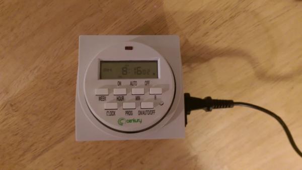
Set the timer switch to energize the feeder at the desired time and the desired duration. Refer to the manufacturer’s instructions on how to program the timer switch.
The feeder with dispense approximately 1/4 to 1/3 cup of food for every minute that it is energized. The amount dispensed may vary depending on the shape and size of feed used.
Step 11: Setup the Feeder
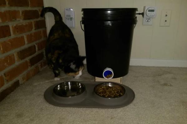
Ensure that the feeder is installed on a level surface to prevent the feed from collecting on one side of the hopper.
Plug it in and remember to check it every couple of days to ensure that it has enough feed in it.
Source: Automated 5 Gallon Bucket Feeder
