Summary of AUDIO VU/SOUND LEVEL METER WITH LM339
This project is a bar-graph Audio VU (sound level) meter using 20 comparators and LEDs to display audio amplitude. The input from an amplifier speaker output and ground drives the comparator chain, biased by a resistor string and a 100K potentiometer to provide reference voltages from 1.9V to 12V. It responds quickly and suits amplifier outputs of about 1W–10W; PR2 adjusts input level and PR1 sets the reference so all LEDs light at maximum signal. Not suitable for low-level line inputs.
Parts used in the Audio VU Meter:
- LM339 comparator IC (or equivalent 20-comparator implementation)
- 20 LEDs
- Resistor string (series resistors for ladder biasing)
- 100K potentiometer (for reference voltage)
- PR1 potentiometer (reference adjust)
- PR2 potentiometer (input audio level adjust)
- Input coupling wiring (to amplifier speaker output and GND)
- Resistors for LED current limiting
- Power supply (providing up to 12V reference)
- PCB or protoboard and connectors
This is an “Audio VU Meter” or “Sound Level Meter”, it is a general-purpose bar-graph Audio VU meter designed for fun projects.
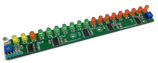
All you need is to hook up one wire to the output of the audio amplifier’s speaker pin along with GND and see the magic. The response of the circuit is very fast and it provides beautiful visual representation from audio input signal.
A simplified schematic is provided to give the general idea of the operation. The signal is applied to a series of 20 comparators, each of them is biased to a different comparison level by the resistor string. In the circuit diagram, the resistor string is connected to the 100K potentiometer which provides reference voltage 1.9V to 12V.
As the input voltage varies from 0 to 1.9V, the comparator’s outputs are driven low one by one, switching on the LED indicators. This circuit will work with the audio signal level from 1.9V to 12V, it will not work with the audio line signal. String resistor values calculated to use this project with audio amplifier of 1W to 10W.
PR2 provided to adjust the input audio signal level. Testing the board is simple, keep both potentiometer PR1 and PR2 at the center, hook-up 2 wires GND and Input signal to Audio amplifier speaker out, adjust the PR1 so all LEDs are in ON condition at the full audio signal level.
Read more: AUDIO VU/SOUND LEVEL METER WITH LM339
- What does the Audio VU Meter use to compare input levels?
It uses a series of 20 comparators biased by a resistor string to compare the input signal to multiple reference levels. - Can the Audio VU Meter be driven from a line-level audio signal?
No. The circuit requires audio signal levels from 1.9V to 12V and will not work with a low-level line signal. - How do you connect the meter to an audio source?
Hook one wire to the amplifier speaker output and the other to GND. - What is the purpose of the 100K potentiometer?
It provides the reference voltage range (about 1.9V to 12V) for the resistor string that sets comparator thresholds. - What range of amplifier power is this project designed for?
The resistor string values are calculated for amplifiers of approximately 1W to 10W. - How do you adjust the display so all LEDs light at full signal?
Set PR1 and PR2 to center, then adjust PR1 so all LEDs are on at the full audio signal level. - What does PR2 do?
PR2 adjusts the input audio signal level entering the comparator chain. - How fast is the circuit response?
The article states the response is very fast, providing a real-time visual representation of the audio input.