
Summary of Audio Function Generator Provides Three Simultaneous Square, Triangle, Sine Waveforms
This article describes a low-cost, robust signal generator using the LM386 IC to produce simultaneous square, triangle, and sine waveforms. It features independent amplitude control for three outputs capable of driving various loads like speakers or transformers. The circuit utilizes an op-amp based square-wave generator, a triangular signal path through potentiometers, and filters (LPF/BPF) followed by amplification to create clean sine waves. Users can switch between two frequencies, making it ideal for testing audio installations and components.
Parts used in the Audio Function Generator:
- LM386 Power Amplifier IC
- R1 Resistor
- C1 Capacitor
- P1 Potentiometer
- Low-pass Filter (LPF)
- Band-pass Filter (BPF)
- IC2 Amplifier
- IC3 Amplifier
- P2 Potentiometer
- Frequency Switch
This simple, robust, and low-cost signal generator, based on the LM386 power amplifier IC, provides a trio of audio-band signals with three different simultaneous outputs at the same frequency: square/rectangle (SQW), triangle (TRG), and sine (SS).
Ramp Generator Uses Microcontroller Emulation Of Unijunction Transistor
Generate A Differential Signal Using A Transformer Plus Signal Splitter
Each output can drive loads such as long cables, transformers, auto-transformers, audio couplers, or active loudspeakers. The amplitude of each output can be adjusted independently. The outputs can be connected to ground, the power supply, or between them for short time without damage.
The generator is useful for checking electrical or audio installations, audio or mains transformers, and similar components. The suggested maximum load for each output is 8 Ω, but lower-impedance loads also can be handled with some reduction in output. As a further convenience, the user can switch the output triplet between two frequencies.
The simplified block circuit shows IC1 operating as a square-wave generator with frequency determined mainly by R1 and C1 (Fig. 1). The signal in point A is approximately triangular with amplitude of about 0.35 V p-p and a supply rail of +9 V.
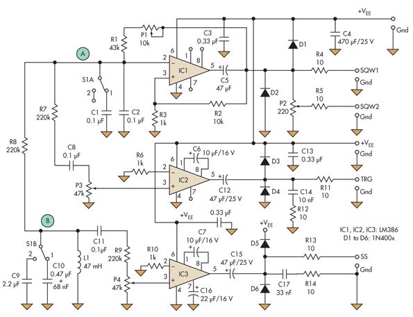
The triangular signal goes to amplifier IC2 via potentiometer P1. It is also routed to the low-pass filter (LPF) or a band-pass filter (BPF). The quality of that filter determines the quality of the sinusoidal signal, which IC3 amplifies.
The 3-dB frequency of the LPF should be equal to or lower than the frequency of the triangular signal at point A. With a BPF, the central frequency or the resonant frequency should be approximately equal to that of the signal at the same point. In the simplest case, these can be second-order low-pass RC, RC band-pass, LC band-pass, or LC low-pass filters. IC3 amplifies the sinusoidal signal at point B, after potentiometer P2.
For more detail: Audio Function Generator Provides Three Simultaneous Square, Triangle, Sine Waveforms
- What signals does this generator produce?
It produces a trio of audio-band signals: square/rectangle, triangle, and sine. - Can the output amplitude be adjusted independently?
Yes, the amplitude of each output can be adjusted independently. - What types of loads can these outputs drive?
Outputs can drive long cables, transformers, auto-transformers, audio couplers, or active loudspeakers. - Is it safe to connect the outputs to ground or power supply briefly?
Yes, the outputs can be connected to ground, the power supply, or between them for short time without damage. - How is the frequency of the square wave determined?
The frequency is determined mainly by R1 and C1. - What determines the quality of the sinusoidal signal?
The quality of the filter (low-pass or band-pass) determines the quality of the sinusoidal signal. - What is the suggested maximum load for each output?
The suggested maximum load for each output is 8 Ω. - Can the user change the operating frequency?
Yes, the user can switch the output triplet between two frequencies.
