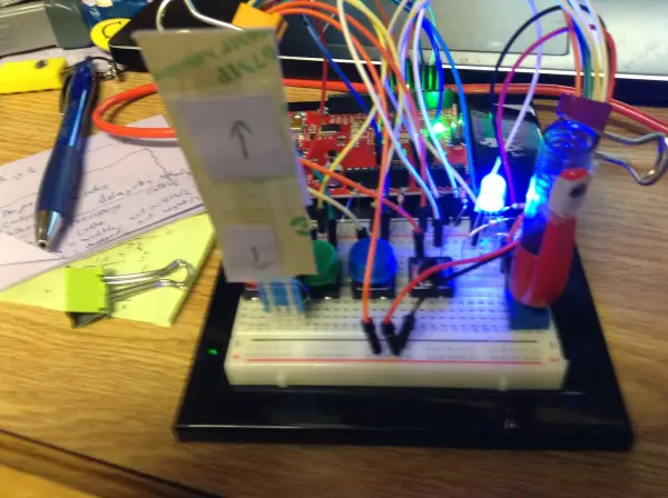
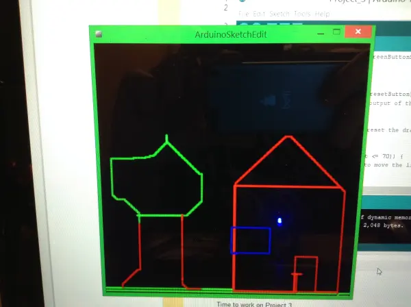
This project, dubbed the Arduino Sketcher, is a straightforward device designed for drawing pictures on your computer screen. Utilizing a processing code and the SparkFun Redboard, it simplifies the process of creating digital art.
Device Description and Functionality
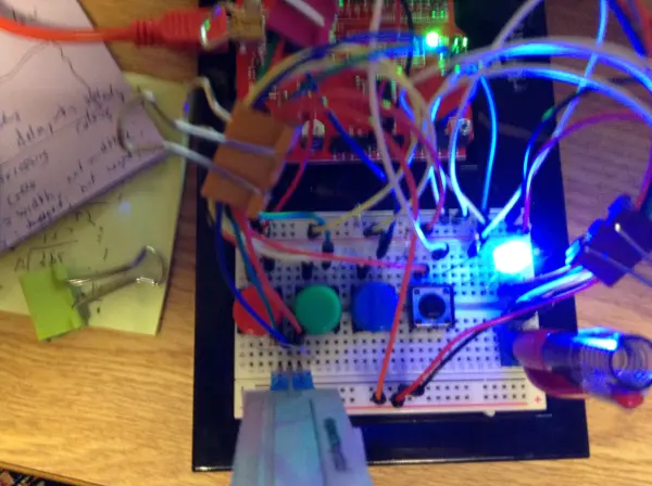
The device consists of four push buttons: red, green, blue, and a neutral button. Each button changes the line color to its corresponding color, while the neutral button resets the drawing. Simultaneously pressing and releasing the red and blue buttons creates magenta, following the same principle for other color combinations. However, this feature is sensitive and can be challenging to operate smoothly.
An RGB LED on the screen indicates the current drawing color. Additionally, a soft potentiometer moves the line up when pressed at the top and down when pressed at the bottom. A standard knob potentiometer adjusts the line horizontally: turning right moves the line right, and turning left moves it left.
Interface Design for Processing Code
The assignment required us to develop an interface for the provided Processing code. This interface needed to facilitate drawing, color changing, and canvas resetting. After careful consideration, I decided to explore using the soft potentiometer as a novel approach for drawing. Initially, I entertained the idea of integrating all four directional controls into one soft potentiometer, leveraging its different zones for each direction. However, I discarded this idea due to concerns about overcrowding the soft potentiometer.
Subsequently, I experimented with using two separate soft potentiometers but found that the knob potentiometer offered a satisfactory interface during testing. Ultimately, I opted to combine the knob potentiometer with the soft potentiometer for enhanced usability.
Early in the design process, I determined that controlling and displaying drawing colors using buttons and an RGB LED would be effective.
Challenges Encountered
While working on the project, I faced several challenges that required troubleshooting. Primarily, it took me some time to devise the correct code to ensure the sketching program drew lines accurately. One significant issue arose from inadvertently using Serial.println() in my code, which disrupted the communication between Arduino and Processing.
Additionally, I encountered a coding issue where a line of code inadvertently reset the drawing position, restricting me to drawing only one line at a time.
Furthermore, there was a wiring mishap at one point. This resulted in the color switching to red whenever I pressed the lower part of the soft potentiometer, instead of the intended functionality.
Building Your Own Arduino Sketcher: Parts List
To construct your own Arduino Sketcher, follow along for sketches, schematics, and code details.
Parts Needed:
- (1) Arduino Uno or SparkFun Redboard
- (1) Solderless breadboard
- (4) Push buttons
- (1) RGB LED
- (1) Soft potentiometer
- (1) Regular potentiometer
- (3) 330 Ohm resistors
- (6) 10K Ohm resistors
- Several wires
These components will form the foundation of your Arduino Sketcher project.
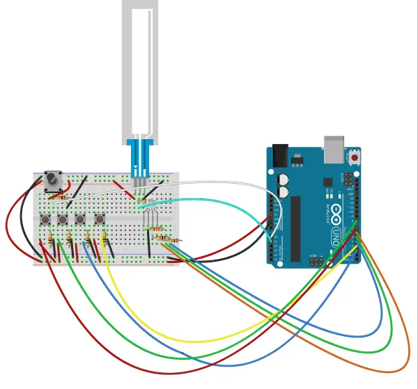
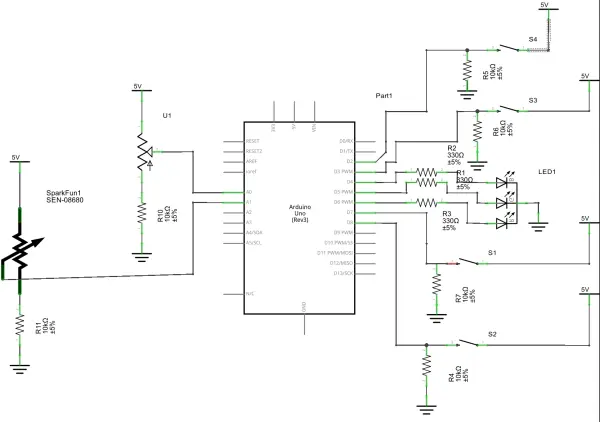
The basic sketch and schematic are below.
Wiring Instructions for Components
Potentiometers:
- Apply 5 volts to the right pin of each potentiometer.
- Connect the middle pin to an analog input pin: A0 for the knob potentiometer and A1 for the soft pot.
- Connect a 10K Ohm resistor from the middle pin to ground.
- Connect the leftmost pin to ground.
Buttons:
- Connect 5 volts to one terminal of each button.
- From the other terminal, connect a 10K Ohm resistor to ground.
- Connect a wire from this terminal to a digital pin (e.g., 7, 8, 3, 2).
RGB LED:
- Connect the ground pin of the RGB LED to ground.
- Use a 330 Ohm resistor to regulate current to the wires connected to digital pins.
- Connect these wires to digital pins for RGB control (e.g., 4, 5, 6).
The Arduino code used can be viewed below.
Code Functionality Overview
The code comments should provide most of the details on its operation. Essentially, the code monitors the status of all devices and triggers corresponding functions when necessary. For instance, when the state of the red button changes, it invokes the colorRed() function, defined as follows:
void colorRed() { //turns the LED and the color of drawing red digitalWrite(LEDblue, LOW); digitalWrite(LEDgreen, LOW); digitalWrite(LEDred, HIGH); Serial.write('c'); Serial.write(255); Serial.write(0); Serial.write(0);}moveDown() as shown below:Project Overview and Improvements
I structured the code to call numerous functions, simplifying the loop() function to trigger actions as needed.
Unfortunately, I can’t share the Processing code, as it was provided by my instructor. However, I made a minor adjustment: I modified the drawing point to extend to the edges rather than the center. This change involved updating prevX from width/2 to width, and similarly adjusting prevY to height.
Reflecting on the project, there are areas for improvement. Mixing colors like magenta, yellow, and cyan has proven challenging, as access to white and black is limited. Attempting to incorporate these colors with just two buttons—pushing and releasing three simultaneously—is impractical. Expanding the project on a larger breadboard with more buttons could resolve this issue. Initially, I had only four buttons, and by the time I realized the limitations of my setup, it was too late to gather additional components.
The knob potentiometer, while functional, becomes uncomfortable over prolonged use. I attempted to address this by fashioning a makeshift knob with a pen, but it occasionally shifts unintentionally, causing drawing glitches. Additionally, the soft potentiometer sporadically registers input without physical contact. This could be due to hardware issues or minor glitches in the code or wiring that might be rectifiable.
Lastly, there’s a noticeable delay when switching colors, which pauses drawing for a few seconds. This delay likely results from the Processing code processing each command and byte sequentially. Eliminating this delay would enhance the project’s responsiveness and usability.
Follow this link for complete project: Arduino Sketcher: Drawing with Processing & SparkFun Redboard

