Summary of Arduino robot kit – Wiring Diagram
This article details a wiring diagram for an Arduino-based robot project, outlining connections between the motor controller, motors, range sensor, servo motor, line detector, and Bluetooth module. It provides specific pin assignments for digital, analog, and power pins to ensure proper integration of these components. The author notes that alternative connection methods exist and advises caution when implementing the diagram.
Parts used in the Arduino Robot Kit:
- Arduino Board
- Motor Controller
- Range Sensor
- Servo Motor
- Line Detector
- Bluetooth Module
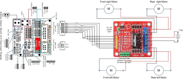
I have created this wiring diagram for the connections between the motor controller, motors, and sensor shield. I’ll update it later to include other components.
And here is an update that includes the servo motor and the range sensor.
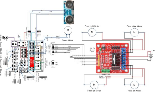
And here are the detailed pin assignments for all modules:
| Arduino Pin | Description | Motor Controller | Range Sensor | Servo Motor | Line Detector | Bluetooth Module |
| VCC | VCC | +5V | VCC | Red | V+ | VCC |
| GND | GND | GND | GND | Brown | G | GND |
| D0 | Digital Pin 0 RX | TXD | ||||
| D1 | Digital Pin 1 TX | RXD | ||||
| D2 | Digital Pin 2 | IN4 | ||||
| D3 | Digital Pin 3 (PWM) | ENB | ||||
| D4 | Digital Pin 4 | IN3 | ||||
| D5 | Digital Pin 5 (PWM) | IN2 | ||||
| D6 | Digital Pin 6 (PWM) | ENA | ||||
| D7 | Digital Pin 7 | IN1 | ||||
| D8 | Digital Pin 8 | S | ||||
| D9 | Digital Pin 9 (PWM) | Orange | ||||
| D10 | Digital Pin 10 (PWM) | |||||
| D11 | Digital Pin 11 (PWM) | |||||
| D12 | Digital Pin 12 | Trig | ||||
| D13 | Digital Pin 13 | Echo | ||||
| A0 | Analog input 0 | |||||
| A1 | Analog input 1 | |||||
| A2 | Analog input 2 | |||||
| A3 | Analog input 3 | |||||
| A4 | Analog input 4 | |||||
| A5 | Analog input 5 |
Disclaimer:
The diagrams above are not the only way you can connect the components so use at your own risk.
For more detail: Arduino robot kit – Wiring Diagram
- Which Arduino pins are assigned to the Range Sensor?
Digital Pin 12 is connected to Trig and Digital Pin 13 is connected to Echo. - How is the Servo Motor connected to the Arduino?
The orange wire connects to Digital Pin 9 which supports PWM output. - What pins handle the Bluetooth Module communication?
Digital Pin 0 RX connects to TXD and Digital Pin 1 TX connects to RXD. - Which pins control the motor direction inputs?
IN1 uses D7, IN2 uses D5, IN3 uses D4, and IN4 uses D2. - Can I use different wiring configurations than shown?
Yes, the diagrams are not the only way to connect the components so users should proceed at their own risk. - Where do the VCC and GND lines connect?
VCC connects to +5V or Red wires while GND connects to Brown or GND labels across all modules. - Does the Line Detector use any analog inputs?
No, the provided table shows the Line Detector S pin connected to Digital Pin 8.