Everybody wants to know how many pageviews your own website has. But see what’s happening you need some analytics code and stuff like this. I wanted to be connected to the wold when I’m sitting on my couch so I connected my Lucky Cat to the internet.
Whenever someone visits a page on my website www.janhimself.de the cat waves it’s arm for a while. At night though I need some silence. So I built in a RGB LED which changes its color whenever a new pageview happens.
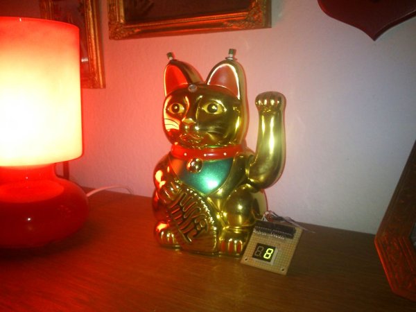
a Lucky Cat
an arduino ethernet
a RGB LED
two small yellow LEDs
a light sensor
a servo
Step 1: The Servo
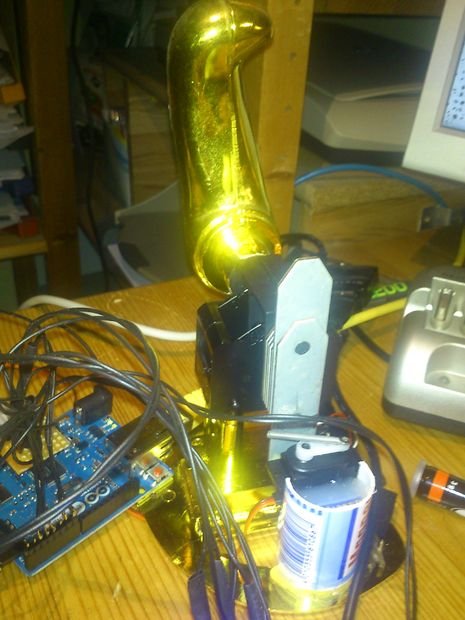
The mechanical part is easy: opening up the cat you can see the counterweight of the arm. When the servo turns, the spring hits the counter weight of the arm and the arm swings for something like 20 seconds. I use some hotglue and part of a small plastic thingy to place the servo beneath the cats mechanics.
(I coded something like a time delay into the software part, so that the servo does only swing the arm once every 20 seconds. So if there would be multiple pageviews in that time, the counter would count them, but the arm just moves every 20 seconds until the work is done)
Step 2: Buttons and LEDs
I used two buttons:
button one is connected to Ground (GND) and the reset pin of the arduino.
The second one is to manually start the RGB LED, because it’s always fun to change the color of an LED. It’s connected to Pin 7 and +5V. And to pull the pin low there’s a resistor (10K) connected to GND.
The RGB LED is connected to Pin 17 to 19 on the arduino. (Would be better to connect them to the PWM pins)
The yellow LEDs are attached to Pin 16
The servo is attached to Pin 6 (and +5V and GND)
The display uses Pin 2 as LatchPin, Pin 3 as DataPin and Pin 4 as ClockPin. It’s juice it gets from +5V and GND
The light resistor is attached to analogue pin 1 and +5V and to GND using some resitors (2.4K)
Choose the correct resistors for your leds for example by using ElectroDroid on your smartphone.
For more detail: Arduino powered Lucky Cat as physical Webcounter