Summary of Arduino Motion Detector using PIR Sensor
This article explains how to build an Arduino-based motion detector using a PIR sensor. When movement is detected, the system triggers an LED and a buzzer. The project details the sensor's operation modes (H and I), circuit connections, and provides the necessary Arduino code to monitor digital input and control output devices.
Parts used in the Arduino Motion Detector:
- PIR Sensor Module
- Arduino UNO
- LED
- Buzzer
- Breadboard
- Connecting Wires
- 330 ohm resistor
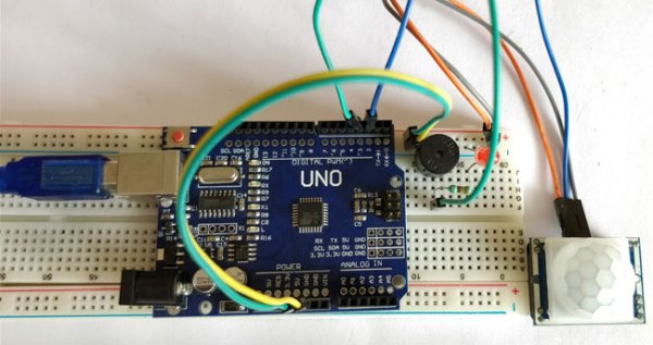
Detecting motions or movements has always been important in most projects. With the help of the PIR Sensor it has become very easy to detect human/animal movements. In this project we will learn how we can interface a PIR Sensor with a microcontroller like Arduino. We will interface an Arduino with PIR module and blink a LED and beep a Buzzer whenever a movement is detected. The following components will be needed to build this project.
Materials Required:
- PIR Sensor Module
- Arduino UNO (any version)
- LED
- Buzzer
- Breadboard
- Connecting Wires
- 330 ohm resistor
PIR sensor:
The PIR sensor stands for Passive Infrared sensor. It is a low cost sensor which can detect the presence of Human beings or animals. There are two important materials present in the sensor one is the pyroelectric crystal which can detect the heat signatures from a living organism (humans/animals) and the other is a Fresnel lenses which can widen the range of the sensor. Also the PIR sensor modules provide us some options to adjust the working of the sensor as shown in below image.
The two potentiometers (orange color) are used to control the sensitivity and trigger on time of the sensor. Basically the Dout pin of the sensor is present in between the Vcc and Gnd pins. The module works on 3.3V but can be powered with 5V as well. On the top left corner it also has a trigger pin setup which can be used to make the module work in two different modes. One is the “H” mode and the other is the “I” mode.
In “H” mode the output pin Dout will go high (3.3V) when a person is detected within range and goes low after a particular time (time is set by potentiometer). In this mode the output pin will go high irrespective of whether the person is still present inside the range or has left the area. We are using our module in “H” mode in our project.
In “I” mode the output pin Dout will go high (3.3V) when a person is detected within range and will stay high as long as he/she stays within the limit of the Sensors range. Once the person has left the area the pin will go low after the particular time which can be set using the potentiometer.
Note: The position of potentiometers or pins may vary based on your PIR sensor vendor. Follow the Silk screen to determine you pinouts
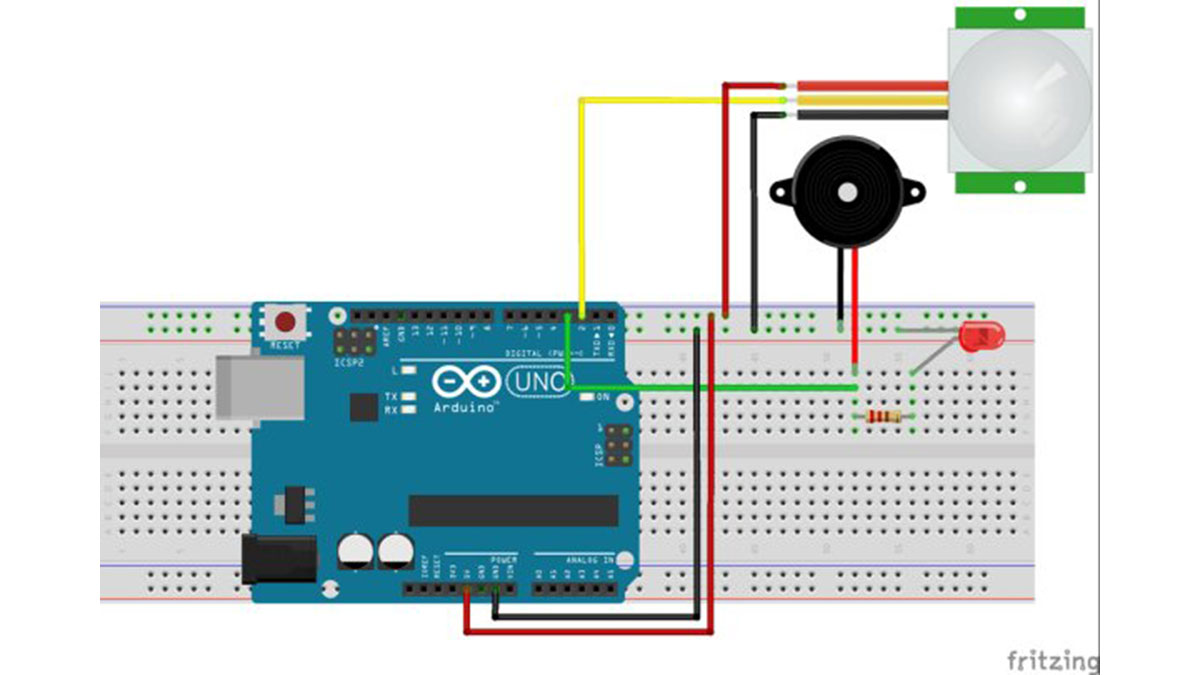
Circuit Diagram and Explanation:
The circuit Diagram for arduino motion detector project by interfacing Arduino with PIR module and blinking an LED/Buzzer is shown in the below image.
We have powered the PIR sensor using he 5V Rail of the Arduino. The output pin of the PIR Sensor is connected to the 2nd digital pin of Arduino. This pin will be the INPUT pin for Arduino. Then the 3rd pin of Arduino is connected to the LED and Buzzer. This pin will act as the output pin of the Arduino. We will program the Arduino to trigger an Output on 3rd pin if an Input has been detected at 2nd pin. The complete Program is explained below.
Programming the Arduino:
The program for Arduino is pretty simple and straight forward. To connect Arduino PIR Sensor, we have to assign the pin number 2 as input and pin number 3 as output. Then we have to produce a discontinuous trigger whenever the pin 2 goes high. Each line is explained below.
In the void setup function shown below, we have to declare that the pin 2 connected to PIR output will be used as input and the pin 3 connected to LED/Buzzer will be used as input.
void setup() {

  pinMode(2, INPUT); //Pin 2 as INPUT

  pinMode(3, OUTPUT); //PIN 3 as OUTPUT

}
Then we proceed to the loop() function. As we know the code in here gets executed as long as the MCU is powered on. So we always check if the Pin 2 has gone high by using the below line inside the loop() function.
if (digitalRead(2) == HIGH)
If we find that the particular pin has gone high, it means that the PIR module has be triggered. So, now we has make our output pin (pin 3) to go high. We turn this pin on and off with a delay of 100 milli second so that we can attain the flashing or buzzing output. The code to do the same is shown below.
Read more: Arduino Motion Detector using PIR Sensor
- How does the PIR sensor detect movement?
The sensor uses a pyroelectric crystal to detect heat signatures from living organisms and a Fresnel lens to widen its range. - Can the PIR module be powered with 5V?
Yes, although the module works on 3.3V, it can also be powered with 5V. - What is the difference between H mode and I mode?
In H mode, the output goes high when a person is detected and stays high for a set time regardless of their presence; in I mode, the output stays high only while the person remains within the sensor's range. - Which Arduino pin is used as the input for the PIR sensor?
Pin number 2 is assigned as the input pin connected to the PIR sensor output. - Which Arduino pin controls the LED and Buzzer?
Pin number 3 is configured as the output pin to trigger the LED and Buzzer. - How often does the LED flash or buzzer beep upon detection?
The output pin turns on and off with a delay of 100 milliseconds to create the flashing or buzzing effect. - What materials are required to build this project?
You need a PIR Sensor Module, Arduino UNO, LED, Buzzer, Breadboard, Connecting Wires, and a 330 ohm resistor. - How do you adjust the sensitivity of the PIR sensor?
The two orange potentiometers on the module are used to control the sensitivity and trigger on time.