I finally finished my Arduino Monitor/Tester!
This is how it turned out to be:
- One LED for every single input or output
- Can be used with Uno, Leonardo, Mega, Due, Mini, etc.
- Also fits with my universal I/O board
- Power taken from Arduino 5V and 3.3V outputs, and the Vin
- Load on any pin is 10 kohm or more
- LED intensity proportionally reflects the pin voltage or duty cycle
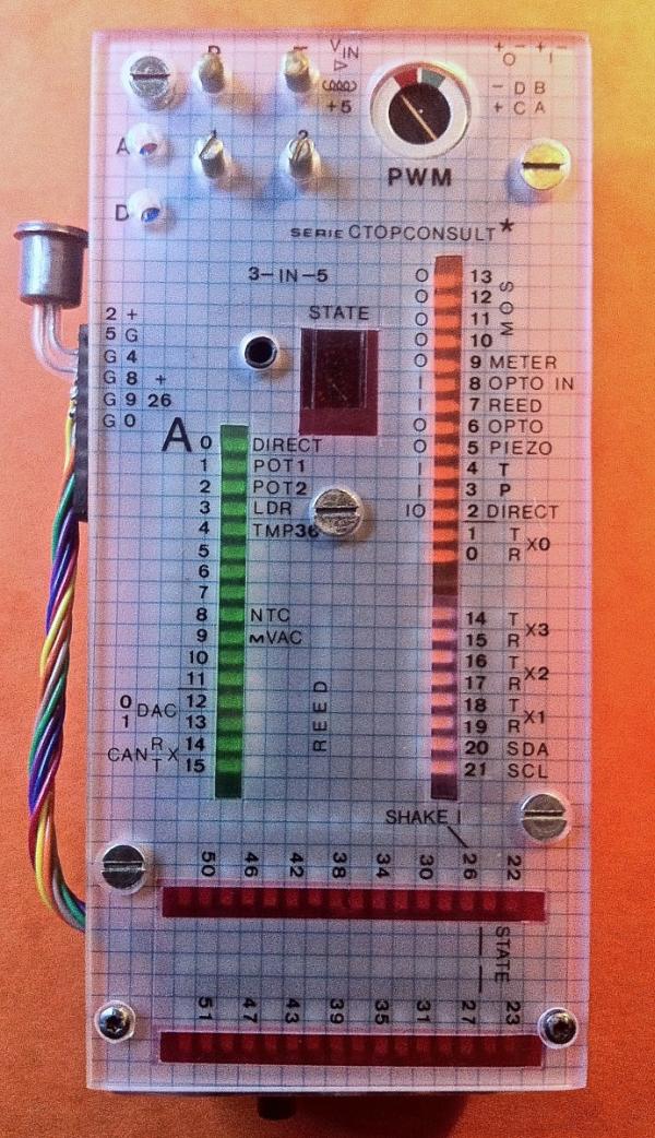
- Builtin inputs and outputs for testing new ideas:
- One pushbutton (P) to digital input
- One toggle switch (T) to digital input
- Two potentiometers (1, 2) to two analog inputs
- 4 digital outputs to HEX-display (e.g. for program STATE output)
- Very small moving coil voltmeter on PWM output
- Piezo loudspeaker on PWM output
- 4 digital outputs to open-drain MOSFET (builtin flyback diodes)
- One opto-isolated digital input
- One opto-isolated digital output (not for 230 VAC)
- One direct analog input via miniature LEMO coax connector
- One direct digital I/O/PWM via miniature LEMO coax connector
- One reed-relay (no coil) to digital input
- One mercury shake alarm to digital input
- One TMP36 temperature sensor to analog input
- One electret microphone to analog input (x 100 gain)
- One NTC resistor to analog input (linearized)
- One light-dependant resistor to analog input
- All inputs and outputs can be made passive to enable inputs from other sources
- LED’s grouped in 16 for analog I/O, 14 for digital I/O/PWM, 8 for digital I/O/Tx/Rx and 32 digital I/O. In total 70 LEDs.
- All LEDs are very high efficiency white SMD types with coloured film on top, according to the group.
- The LEDs cathode reference can be adjusted down to -2V: LEDs will start to light up when pin voltage goes positive.
- The cathode reference is divided into one for analog and one for digital, adjusted individually
- Maximum input voltages can be selected between 5V or 3.3V to fit with DUE board
- Voltage for internal circuits and steppermotor outputs can be selected between 5V and Vin
- IC-sockets and Arduino pins are all gold plated
- LEMO I/O, Shake-sensor, NTC, TMP36, microphone and piezo-speaker are in a detachable separate module
Here you can see the separate compartment with the two LEMO connectors, TMP36 and NTC temperature sensors, and a blue LED indicator for 5V. The piezo-speaker and microphone is on the side facing down (see the next picture). The shake-sensor you can see on the picture above: It is placed on the connector for the separate compartment.
For more detail: Arduino Monitor/Tester