Counting can be a fun task for young children. Children as young as two may start saying numbers in no particular order. A lot of parents start teaching their kids numbers by counting objects around their home. For example, snacks could be counted as the child eats them or toy cars on the floor could be counted as there are put away for the day.
Eventually children will learn to equate the number symbol (1 – 10) with the number of objects that are counted. In this project, it will be the number of green lights that light up. A set number of LED lights will illuminate for the button number that was pushed by the child.
Step 1: Design
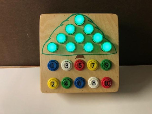
The lights were laid out in a triangular pattern that more or less resembles a pine tree or Christmas tree. The first light or number “1” light will be at the top of the Christmas tree. As the number pressed increases, the number of lights that light up will increase from top to bottom. The number “10” will light up the whole Christmas tree. The number buttons were placed at the bottom of the front panel arranged in two rows of 5 buttons each. Each button had a number value placed on it.
I used 10 green round indicator lights that were purchased on Amazon.
Gasher 12V/24V/110V 20mA Energy Saving Indicator Light Mounting Hole Size 22mm (7/8 Inch) Green 10 Pcs: Amazon.com: Industrial & Scientific
They are rated up to 12 VDC but they worked fine with the 5 VDC that Arduino provides.
I used regular arcade momentary buttons for the child to press. There are large enough for the child’s smaller fingers and have a very reliable switch mechanism.
Amazon.com: WMYCONGCONG 10 PCS Push Button with Micro Switch for Jamma Mame Arcade Video Games DIY: Toys & Games
Other components and materials used were:
· Arduino Mega board
· Misc. wires
· Spade connectors
· 9-volt battery power supply bundle
· On/Off switch
· 2.54mm Single Row Right Angle Header Connectors
· ½” thick birch plywood
Step 2: Building the Box
The counting tree box was made out of ½” thick birch plywood. The front panel was cut square at 9” wide by 9” high. I had to make the box deep enough to accommodate the arcade buttons. Consequently, the sides were cut to a height of 2 inches.
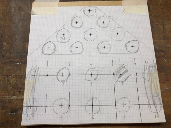
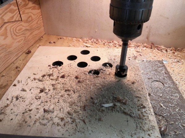
The pattern for the holes was laid out on graph paper and then transferred to the front plywood panel. A nail mark was used to transfer the center of each hole to the panel. The holes were then drilled with a forstner bit to the proper diameter. The diameter for the lights was 7/8” and the diameter for the arcade buttons was 1 1/8”. I needed to countersink the top indicator light holes from the inside because the ½” thickness of the plywood was too thick and covered the threads needed to tighten the plastic nut in place.
Once all the buttons were drilled the top panel was glued to the sides and nailed in place. The inside corners of the box were reinforced with small square wood blocks. The bottom of the box was then fitted and screwed in place. The whole box was then sanded square and the corners were rounded for safety. Everything was sanded nice and smooth with no sharp edges. The box was then finished with tung oil. You could also use polyacrylic or polyurethane. Once dry, the bottom of the box was unscrewed so the electrical components and wiring could be placed.
Step 3: Bench Set-Up
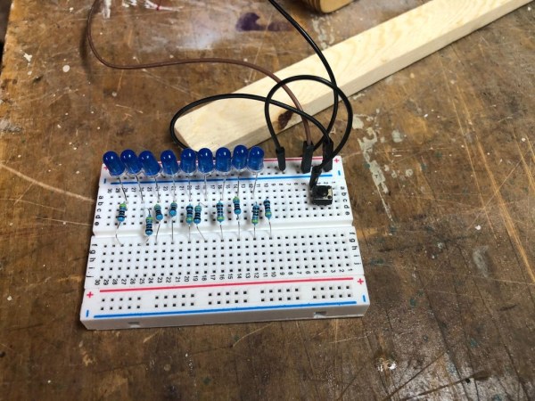
A bench set-up was completed to test all the electrical components and circuits as shown in the accompanying photos. A solder-less breadboard was used to make all the connections. 10 LED lights were positioned with a corresponding resistor for each of them. A couple of momentary buttons were placed to simulate the counting arcade buttons. The buttons and LED leads were connected to the defined pins on the Arduino Mega board. After some modification and edits I was able to get the Arduino code working the way I wanted it.
Step 4: Arduino Code
I needed 20 pins on the Arduino; 10 for the arcade buttons and 10 for the LED lights. For this many pins I needed to use an Arduino Mega board.
The first thing the code does is assign 10 pins as input pins for the arcade buttons. I use the Arduino internal pull-down resistor so the code will look for which button is pulled “LOW”. Each arcade button will be assigned a number of one through ten.
Next, each LED light is assigned to a pin and these pins are designated as output. The ten pins are grouped into a 10 item array with placeholder values of 0 – 9.
The loop() function starts out with a series of “if” statements to discern which button was pushed by the child. Then a variable called “buttonNum” is assigned the numerical value of that button. Then the code will cycle through the LED array with a “for” statement. If the placeholder number of the array is less than or equal to the numerical value of the button pushed, the output of these pins will be turned “HIGH”. All pins in the array after the numerical value will be turned “LOW”.
That is basically it; the first part of the code looks for which arcade button was pushed and the second part of the code turns the assigned numerical value of the button into that number of LED lights switched “HIGH” on the counting tree. This number of lights will stay on until the next button is pushed.
Step 5: Final Assembly
All the indicator lights and arcade buttons were inserted into their respective holes on the front plywood panel. Each corresponding plastic nut was attached and tightened to hold them in place. Next, each light and button needed a ground wire. I connected the 10 arcade button ground wires in series to one another leaving one ground wire to connect to the Arduino and the 10 LED ground connectors in series to another ground wire. The two ground wires were then connected into the two ground pins on the Arduino Mega board.
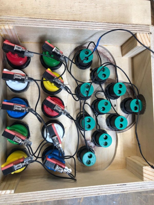
Two 10-wire bundles were made for the button and LED light positive terminals. The arcade buttons required a spade connector be soldered to each positive wire. I used male breadboard terminals for the LED positive connections because they could be screw tightened in place. On the Arduino pin connection end of the wire bundles I used 2.54mm spaced single row right angle header connectors. These held quite firmly in place on the Arduino board. The wire bundles can be seen in one of the attached photos.
I routed out a place in the bottom of the counting box for the Arduino Mega board to be mounted. I didn’t want the height of the Arduino board to interfere with the bottom of the arcade buttons (micro switch part).
The last component to mount was the on/off switch. I countersunk the button in the side of the box that will be orientated as the top so it would be flush. This way, it could not be turned on or off accidentally. The Arduino will be powered by a 9-volt battery. The on/off switch was spliced into the positive side of the battery bundle.
Step 6: Conclusion
Please watch the demonstration of the counting tree in action.
Source: Arduino Based Counting Tree for Children