Summary of ARDUINO AIRGUN CHRONOGRAPH
This project describes building an Arduino-based airgun chronograph to measure pellet speed and energy, using two IR sensor pairs and a 20x4 I2C LCD. It outlines required parts, case preparation, wiring, Arduino programming, sensor tube construction with 60 mm sensor spacing, and final assembly and testing. The design is adaptable and has been used successfully by others; the creator provides the sketch and encourages customization.
Parts used in the Arduino Airgun Chronograph:
- 20x4 character LCD (blue) 2004 with I2C serial interface
- OPL550 IR phototransistors (2)
- OP240A IR LEDs (2)
- Wisher WCA-H2853 case enclosure (or similar)
- Arduino Nano
- Arduino Nano terminal interface PCB or Veroboard (optional)
- MN1604 battery connector
- MN1604 battery
- 5 mm momentary SPST N/O push button switches (2)
- SPST latching on/off push button switch
- 4-pole jack plug/socket lead 2 m (optional)
- Assorted connecting wire
- Velcro adhesive fixing tape
- Nylon Tyraps
- Heatshrink sleeving
- Double-sided LCD fixing tape
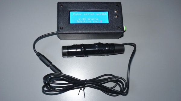
This is a chrono for measuring the speed and energy of an air rifle pellet.
It’s pretty fast and could probably be used for other types of gun, (airsoft , full bore etc) but I have not tested it on them.
I initially made this available as a kit of parts and info, it has been well tested by others and gives accurate results…..but now it’s FREE for all to do as you like with….SO Get Building!
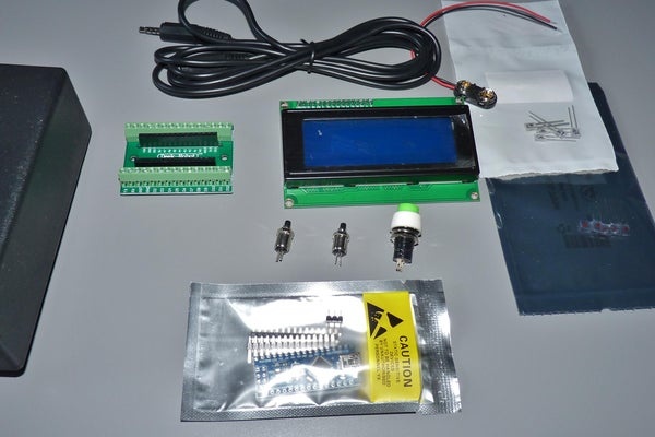
Supplies
CHRONO PARTS LIST
1 20×4 character LCD (blue) 2004 with i2C serial interface
2 OPL550 IR photo transistors
2 OP240A IR LED
1 Wisher WCA-H2853 case enclosure (or similar)
1 Arduino Nano
1 Arduino Nano terminal interface PCB or Veroboard (optional for easier build)
1 MN1604 battery connector
1 MN1604 battery
2 5mm momentary SPST N/O push button switches
1 SPST on/off switch
1 4-pole jack plug/socket lead 2 mtrs (optional for removable sensor tube)
assorted sundries e.g. connecting wire, Velcro adhesive fixing tape,
‘nylon Tyraps’, heatshrink sleeving, double sided LCD fixing tape etc.
Step 1: Lets Begin….
Obtain the parts and components listed from your favourite sources, adapt the instructions to suit the parts that you can find. Some of you could probably use your 3D Printer to make your own ‘custom case’.
Some basic soldering skills will be needed to attach some of the connecting wires, please research ‘how to’ if you are not familiar with soldering. Basically use a hot iron, clean connections and rosin flux cored solder, (I still prefer to use thin 60/40 tin/lead solder)
1. Mark out and carefully cut out the case lid to suit the LCD window. (TIP: if you drill a hole in each corner of the marked window, it makes it easier to saw out the centre using a coping saw or similar. A sharp hobby knife and file can be used to tidy the aperture)
2. Drill two 5 mm holes and fit the two small push button switches. The actual positions are not crucial and are up to you, but take the position of the internal parts into consideration when deciding locations.
3. Drill a larger 9.5mm hole for the latching push ON/OFF switch, and another 3.0mm hole for the sensor jack cable, again taking the internal parts into consideration when deciding a location.
4. The LCD can then be easily attached inside the lid, using a thin strip of double-sided tape around the window aperture. Make sure it’s mounted the correct way up!
Step 2: Get the Soldering Iron Out….
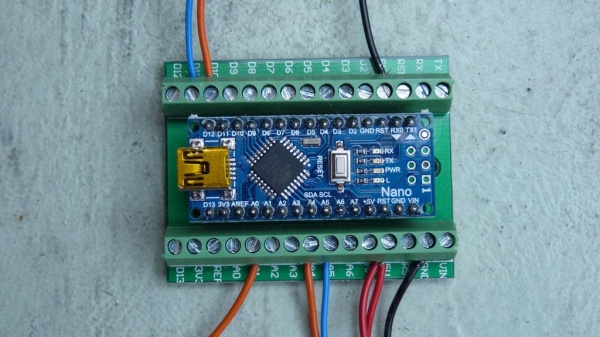
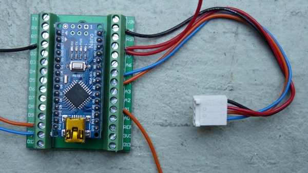
5. Solder the header pins to the Arduino Nano and push it into the terminal board, ensuring correct orientation!
Using the terminal board makes it easy to connect and correct any wiring mistakes, you could use a piece of VeroBoard or solder directly to the Nano.
Connect the battery connector and latching ‘power’ push button switch following the wiring diagram pdf. , leaving sufficient spare wire to allow easy battery removal. Connect the battery power wire to the Vin screw terminal on the Arduino module. NOTE: as there are four or five black or GROUND wires to connect later, it may be best to wait until all are ready to be stripped and twisted together before fitting to the GND terminal.
Step 3: Wiring the Nano….
6. Solder the connections from the two small up/down push button switches, and connect them to the Arduino Nano module, A0, A1, and GND. (leave wires long enough to remove lid)
7. Cut the jack plug/socket cable about 300 mm from the socket end and carefully strip the outer sheath from the internal four wires about 100mm from the cut ends. Put the jack PLUG lead aside for now. Feed the free socket end through the drilled hole and secure with a nylon ‘Tyrap’ to prevent it pulling out.
Strip and connect these wires to the relevant screw connections of the Arduino module, carefully following the wiring diagram: Green to the +5V terminal, White to D11, Yellow to D10, and black to the GND terminal.
Step 4: Connecting the Liquid Crystal Display
8. The LCD module can now be connected to the Arduino module using a ‘Molex’ connector, or soldering wires directly to the pins, ensuring that the pin marked GND goes to GND terminal, Vcc goes to the +5V terminal, SDA to A4 and SCL to the A5 terminal.
Step 5: Time to Program Your Arduino Nano…
9. Download the Chrono sketch to your computer system, and connect the Nano to the USB. (you may need to select the select the ‘old bootloader’ option and the correct COM port for the board.)
10. Have a look at the sketch and ensure you have all the libraries installed, check line 177 and modify if necessary, the sensor spacing distance that you will be using (default is 60mm).
11. Upload the program sketch to the Nano.
Step 6: Ignition Sequence Starts….
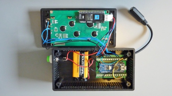
12. The Module and battery can now be fixed in place in the case using self adhesive Velcro strips, a 9 Volt alkaline battery fitted and the unit switched on to test your work.
You may need to adjust the small ‘contrast’ pot on the LCD board for the best image.
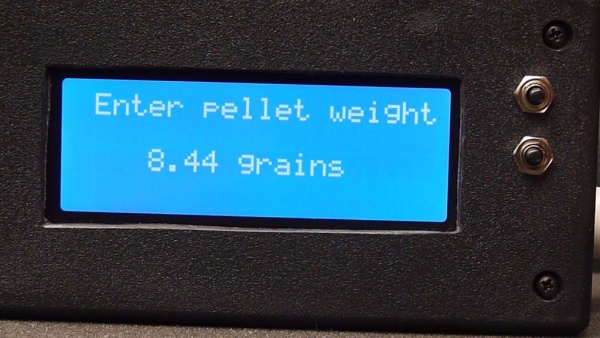
Holding down the ‘up’ button at switch on will allow the actual pellet weight to be entered.
Step 7: The Rifle Sensor Tube….
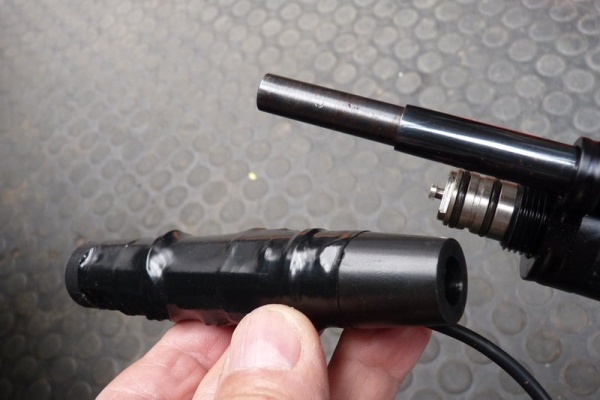
13. Now see the instruction sheet showing one way of constructing the ‘sensor tube’ for your airgun. You may adapt this part as required to fit, the only criteria is keeping the 60mm spacing distance between the two infra-red sensors, (unless the program sketch is modified to suit). Some heatshrink tubing can be used to cover the IR sensors when fitted to the tube. Dropping a pellet down the tube will test the unit, but the values will be very low!
Some of those who have already made this project, have 3D printed their own case and sensor tube. Some have dispensed with the connecting cable and fitted the display etc to the sensor tube…..the options are endless.
I hope you have fun building and using your own chronograph.
Source: ARDUINO AIRGUN CHRONOGRAPH
- What spacing should the two infra-red sensors have?
The default sensor spacing is 60 mm and can be changed in the sketch at line 177 if required. - How is the LCD connected to the Arduino Nano?
Connect GND to GND, Vcc to +5V, SDA to A4 and SCL to A5 (using the I2C interface). - Can I adapt the case or sensor tube design?
Yes, you can adapt the case and sensor tube; some builders 3D printed custom cases or altered wiring/layouts. - How do I enter the pellet weight?
Hold down the up button at switch on to allow the pellet weight to be entered. - What power connection is used for the Arduino Nano?
Connect the MN1604 battery via the battery connector to the Vin screw terminal on the Arduino module. - Do I need soldering skills to build this?
Yes, basic soldering is needed to attach wires; the guide recommends researching soldering techniques if unfamiliar. - How do I connect the sensor jack cable to the Nano?
Strip the socket end wires and connect Green to +5V, White to D11, Yellow to D10, and Black to GND on the Arduino. - What should I check before uploading the sketch?
Ensure correct COM port and old bootloader option if needed, install required libraries, and verify sensor spacing value in the sketch.