Fruit and vegetable market is a big sector that is worth more than 200 billion euros worldwide, this is expected to grow even more in the next decade due to an increasing healthier lifestyle across different European countries. When fruits and vegetables are sold at the supermarket they are usually exposed in open spaces, anyone can touch and handle them.
After the current Covid pandemic, people and institutions will require higher standards of hygiene to reduce the spread of future possible diseases. Even if there is no evidence of transmission of Covid 19 through the surface of fruits, it is good to prevent this possibility, also for further viruses that might arise. Offering to costumers the possibility to feel safer because they buy fresh products that are isolated from possible infecting vectors is a positive aspect that should be considered.
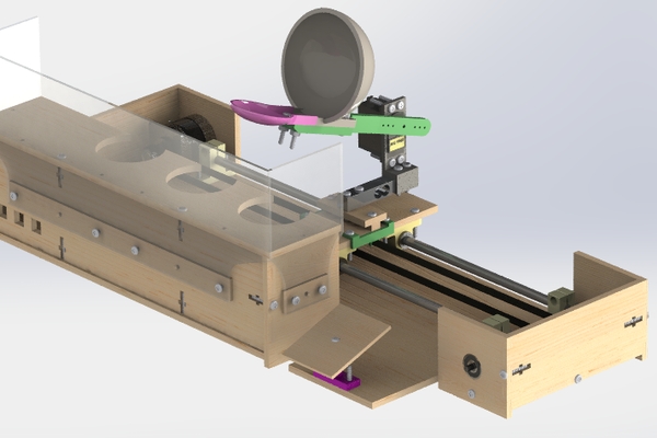
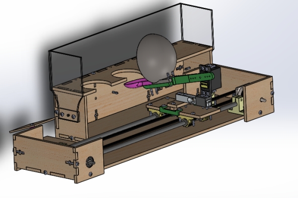
The aim of the following project is to prove the concept that it is possible to deliver and weight fruits and vegetables for clients in a more hygienic way in a supermarket. This project, in particular, consists of a robotic arm that translates on a cart and is able to pick up, weight and deliver inside a bag an apple to the client. The client is also able to select which of the three apple he wants by pressing on different buttons.
Moreover, the supermarket could benefit from having an automated system for fruits and vegetables delivery since this system would ensure a correct and honest weighting of the product.
The realized product is just a prototype made during the course “Mechatronics 1” of the Bruface programme in Electromechanical engineering in Brussels at VUB and ULB. This prototype can be implemented to make it a marketable product. It works only with 3 apples and there is no display to show the weight results. A more detailed development of this final product was conducted during the course “Design Methodology” also part of the Electromechanical engineering program.
Step 1: Conceptual Solution
To Ideate a way to achieve higher standards of hygiene for the delivery of fruits and vegetables, different possible solutions were proposed and analysed. Several gripping systems were designed and experimentally tried. Moreover we conducted multiple researches and we consulted the EU patent website to try to find similar existing products that could be improved for this goal. Nevertheless it was not possible to find similar existing products, these do not exist yet, or some draft ideas were still under development.
The most convenient solution consists in a gripping arm that exploits the force of gravity to secure the apple and delivers it. While the arm rotates, the apple is lifted, and when the arm reaches a vertical position, the apple falls in a semi-spherical cavity that holds the fruit. Using this configuration, it is possible to pick up the apple without damaging it and without risking of dropping it. Furthermore, by taking advantage of the gravity force it is possible to reduce the degrees of freedom of the gripper, making it simpler and easier to maintain.
To exploit the force of gravity, a compatible base is needed so that it is able to hold the apple in the static position, and at the same time to allow the gripper to pass under it to lift the fruit. For this reason, a quasi circular holding system was realized to position the apple during the static position phase. In this way the gripper can pass easily through the hole and lift the apple simply by rotating the arm.
The gripper arm is rotated by a servomotor that is mounted on a load cell. This component is present for two reasons:
- It gives the weight of the apple once it is lifted, the correct weight can be obtained by subtracting the load measured by the cell before the apple is lifted ( weight of the apple and arm) from the total weight measured after the apple is lifted
- The load cell works as a feedback sensor, if the load cell does not measure any added weight it means that there is no apple in that position and the robot can return to its starting position
The load cell was then mounted on a cart that is moved by a timing belt actuated with a stepper motor, in this way it is possible to move the apple from the starting position to where a bag is present and then rotating it in the opposite direction in order to deliver the apple in the bag.
Three buttons are used by the client to select the apple he or she prefers, while a Plexiglass barrier separates the fruit from possible external contamination.
Step 2: Mechanical Design
We modeled our robot using Solidworks student version. Below are some key points of the design.
- Base table
This set of components constitutes the skeleton of the robot. Almost all the major fixations between the different pieces were designed with respect to the base. The five wood plates that make the table are:
- The apple holder, under which the apples are positioned
- The front plate, to support the upper plates and the apples
- The side plates (left and right) to reinforce the parts together and prevent any unwanted movement of the base
- The bottom plate, which is the piece that support the entire components of the robot
- The protective shields (Center and sides), to secure the operative zone of the robot and prevent the user in case of unexpected behavior of the gripping arm
Note that a small elevation is included in the design (6mm from the ground) to be able to put the screws between the bottom pate and the rest of the pieces
2. Structures
The following set are used to relate from one side, the linear actuator, and from the other side, the structure shaft maintains the right timing belt tension and provides one rotational degree of freedom to close the loop in order for the cart to translate between one end of the base to the delivery space.
The back plate of the actuator structure is the same piece that maintains the base together. We went with such a choice to reduce the number of plates used, hence, optimizing the design and avoid unnecessary components. The structure is also fixed together using a left and a right plate, with the right plate slightly higher than the left one to make sure that the elevation of bottom plate is respected.
As in the other structure, it contains three members; a back plate, and two side plates to ensure the shaft related to the belt is properly fixed with holes to account for the radial bearings
Additionally, the structures also contain two shaft supports fixed to the bottom plate to keep the linear motion within its proper range.
3. Cart
The cart is a system consisting of:
- A plate that supports other elements such as the load cell, the servo motor and the entire gripper
- 4 linear bearings for a translational degree of freedom intended to move the gripper left and right and to the delivery space. At first, we worked with only 2 bearings. However, the cart plate was not fully aligned with the horizontal plane. Thus, we increased the number to 4 so that the translation is done smoothly and to avoid damaging the shaft
Above the cart are fixed the components of the gripper. This includes:
- A load cell to measure the weight fixed on a small piece of wood since the cell cannot directly be fixed to the cart, otherwise it will not bend and thus not being able to measure the weight
- A servo mount. This element is crucial to the gripping system because it is the liaison between the load cell and the gripping components (Servo motor, arm, semi-sphere cavity, and the holder). We designed this piece with much consideration because it has to sustain the loads of all the elements mentioned before. In addition to that, due to its irregular geometry, it was almost impossible to realize it using standard wood as it requires more fixations which may not support the amount of shear stress resulting from its contact with the load cell
4. Delivery space
This space was designed to deliver the lifted apple to the customer. the floor was included in the design of the bottom plate to avoid having separate plates that will require additional fixations. The space also contains a slope consisting of a cylindrical base with an oblique extrusion cut making 20° angle with the horizontal ground. The base is joined to a rectangular plate so that the apple does not hit the ground but runs slowly to the customer’s grocery bag.
5. Wood joining methods
To ensure that the whole robot body is rigid and can sustain important loads, we used 2 methods as follows:
- Rectangular patterns: This method consists of adding a tab in one wood plate, and cut a slot with the same geometry on the other wood plate that one wants to join together. Fortunately, this method is easy to implement using Solidworks function “Tab and Slot”
- T-slot screw: the rectangular pattern already provides enough constraints to completely lock the DOFs of 2 wood plates. However, sometimes the tabs tend to “play” inside its slot which give rise to some vibration issues. To ensure this will not be the case, we used an additional method consisting of designing a T-slot in which a screw is inserted, and a nut is added to press on the sides of the plates and completely fixed them together while the nut is then “trapped” inside the slot
6. Manufacturing methods
Available machines in the Fablab:
- 3D printers: used to print small pieces that are not intended to sustain high loads
- Laser cutting machines: used to cut the wood plates to make the robot’s frame
– 6mm/3mm wood plates
– 3mm Plexiglass
– M4x20/M2x10 screws crosshead
– M4x3 nuts
Access Solidworks parts and assemblies files HERE
Step 3: Electronics Design
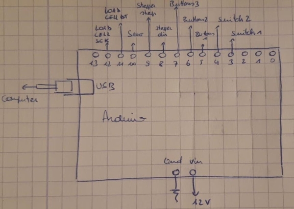
– 1 Arduino uno
– 2 limit switches
– 3 push buttons
– 5 100kohm resistors
– 1 load cell 1kg
– 1 HX711
– 1 100uF capacitor
– 1 A4988 stepper driver
– 1 RS 440-458 (NEMA 17) stepper motor
– 1 buck converter
– 1 MG996R servo motor
The electronic circuits goes as follow :
Buck protoboard :
- A 12V line connected to the power source (hence delivering 12V), to the Vin pin of the Arduino to alimentate it, to the Vmot pin of the A4988 driver to alimentate the stepper motor and to the In+ pin of the buck converter.
- A 5V line connected to the buttons protoboard, the switches protoboard, the Vdd pin of the A4988 and to the servo motor + load cell protoboard. It is used to alimentate the servo motor and give a logical HIGH to the sensors.
- A common ground line to connect the grounds of every protoboards and the ground of the arduino.The electronic circuits goes as follow :
Buttons protoboard :
- All the up right pins of the buttons are connected together and connected to the 5V line of the buck protoboard.
- The down left pin of each button is connected to a 100kohm resistor, used as pull-down resistor, the second leg of these resistors are connected together and connected to the ground of the buck protoboard.
- The voltages between the resistors and the push buttons are send through wires to digital pin 5,6 and 7 of the Arduino.
Switches protoboard :
The circuit is the same as the one for push buttons. The c pins are connected to 5V and no pins to the resistors. The switches are connected to digital pins 3 and 4 of the Arduino.
Stepper protoboard :
- The grounds are connected together and connected to the ground line of the buck protoboard, Vmot pin is connected to the 12V line.
- A capacitor (100 uF) is connected in parallel to the Vmot and ground line to avoid voltage spike that could damage the driver.
- The Vdd pin is connected to the 5V line of the buck protoboard.
- The stepper motor is connected to the pin 1A,2A,1B,2B of the A4988 driver.
- The dir and step pin of the driver are connected respectively to digital pin 8 and 9 of the Arduino.
- The reset and sleep pins are connected together such that they have no influence.
Servo+Load cell protoboard :
- The Vcc pins of the load cell amplifier and the servo motor are connected together and connected to the 5V line of the buck protoboard. The same goes for the grounds, connected to the ground line of the buck protoboard.
- The load cell is connected to the E+,E-,A+,A- of the HX711 load cell amplifier.
- The DT and SCK pins of the load cell amplifier are connected respectively to the digital pins 11 and 12 of the Arduino.
- The control pin of the servo motor is connected to the digital pin 10 of the Arduino.
Arduino :
The Arduino is alimentate through its Vin pin by the 12V line of the buck protoboard. A computer must be connected to the Arduino to enable the serial communication to display the weigh and price of the apple.
Step 4: Arduino Code
The code can be find on the following github : https://github.com/MaximeBussios/Apple-gripper.git
It goes as following :
Functions :
- move_stepper1(int n, bool dir)
move the stepper motor in the direction dir of n steps.
- move_stepper2(int Lswitch, bool dir)
Move the stepper motor in the direction dir until it reaches the limit switches connected to the pin Lswitch.
- move_servoup(int angle)
Move the servo motor to reach vertical position. It is done in multiple steps to reduce the speed of the motion, the delay inside the function lead the speed of the process.
- move_servodown(int angle)
Move the servo motor to reach the position below the apples. Same remark as previously apply for the speed.
- reset(int n)
Set of functions that move the gripper from the delivery place to the place below the apples, the arm is set vertically to doesn’t collide with other parts, the cart reaches first the left switch to get absolute position. It is preferable to reach first this position before going further as the next step is nearer that switch than the other one, leading to fewer steps made “blindly” hence fewer chance to miss steps. Then the cart goes to the position where the apple has been taken, the arm is set down and the cart goes to the far left, its initial position.
Loop :The loop consist of waiting a button to be pressed, the first one leads to take the first apple, the second one to the second apple and pushing the 2 together to the third apple. Normally a third buttons should be present but due to lack of time it hasn’t been implemented so this solution has been found.Once a button is pressed, the cart reach the position of the apple, the arm goes vertically, the cart goes to the delivery place, the arm is put down and then the reset function is called.
Discussion :
As a switch didn’t work in the last 30 minutes before the end of the project, a way to overcome this problem had to be find. In order to do so, instead of reaching it through stepper_move2, the number of step between the 2 opposite sides have been computed and the stepper_move1 function is call instead.
The load cell program hasn’t been implemented due to the fact that a working load cell has been found too late to work on it in addition to the different problems rising. It should normally weigh the apple once the arm is lifted vertically, before reaching the deliverable place. A serial communication with a computer should be implemented also to display the weigh of the apple on the serial monitor of the Arduino software. (Serial.begin(9600); in the setup() and Serial.println() in the delivery function without forgetting to put the serial monitor to 9600 BaudRate).
Step 5: Experimental Results
Take delivery backwards movement
With roughly 30-40 hours of work in a Fablab, with only two people allowed at the beginning and then all the four of us present, it was possible to achieve good results. The robot is able to lift an apple, transfers it from where it is positioned to where the bag is. Nevertheless the system needs to be improved, some electronic components need to be attached to the structure as it can be seen from the video, and a proper working velocity has to be set. Moreover the load cells that were tested did not properly work because they had some damages, therefore it was not possible to accurately weight the apple. However, it is possible to conclude that the goal was achieved: a system that can deliver apples in a supermarket maintaining high hygienic standard was developed. Also, the weighting function can be easily implemented by substituting the broken load cell with a new one of the same type, that can be found on the market for less than 15 euros.
Step 6: Problems Encountered
- The load cell is implemented in the design but it is not working because the first 2 load cells provided were not working and we have found a supposedly working one too late.
- A switch does not work. It worked properly until the last 30 minutes of the project, making the investigation hard to do, especially because other technical problems that never happened before appeared at the same moment.
- The pulley attached to the stepper is a bit too small for it, leading to a poor alignment of the belt. It worked fine but the transmission is thus non perfectly linear, slowering down the translation and leading to extra noises. At first, we thought that the bigger one we had would be good enough but the fact that the pulley and the shaft of the stepper are not concentric had led to a de-tensioning of the belt in every single trial, forcing us to use a smaller one.
- One button is missing due to lack of time. However the 3 apples can be selected by either pressing one of the two buttons or the two at the same time.
- The gripper collides on the structure, this problem has arisen on the last hour before the delivery yet we did not have the opportunity to investigate it. However in all the videos (except for Take, delivery and coming back) involving the motion of the gripper, it can be seen that it does not collide,so it must be a minor problem coming from a mistake while demounting/remounting the support for the apples.
- The protoboard attached to the cart must be moved by hand. A place for it is present on the cart but 3 too short wires cause the problem. A soldering of 3 longer wires can easily fix the problem.
- It can be seen in the video Take, delivery and coming back that the gripper at the beginning does 2 times the expected movement, with the first time being not at the commanded speed. In general the robot has not shown such behavior but it does exists, therefore some debugging must be done to overcome that problem.
Source: Apple Gripper