Summary of AM Shortwave Transmitter
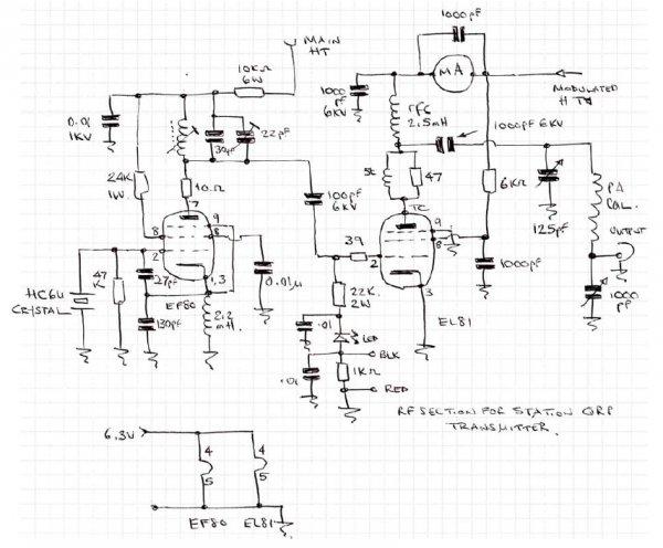
This article describes an 8 Watt AM shortwave transmitter project by Station QRP, intended for educational RF design purposes. It emphasizes legal compliance, requiring a dummy load during operation and prohibiting unlicensed transmission. The circuit uses specific vacuum tubes for the oscillator and power amplifier stages, powered by a high-tension supply of 300 volts at 300 mA. Parts are available from surplus dealers or salvageable from old radios.
Parts used in the 8 Watt AM Shortwave Transmitter:
- Oscillator Tube (6BX6 or EF80)
- Power Amplifier Tube (6CJ6, 6DR6, or EL81)
- HT Power Supply (300 Volts at 300 mA)
- Dummy Load
IMPORTANT: The published circuit diagrams of Station QRP are for educational purposes only. These are offered for the furtherance of the readers’ knowledge regarding Radio Frequency design and principles. At all times during operation an assembled unit must be connected to a dummy load.
In most countries law prohibits the unlicensed operation of transmitters w hen connected to an antenna or even to have such equipment
present in a fully or partially installed state. All responsibilities for the ultimate use of the diagrams are bornesolely by the builder and/or operator 8 Watt QRPAM Shortwave Transmitter Are you interested in building this 8 Watt AM shortwave transmitter?
Most parts used in this transmitter are still available (e.g. Surplus Sales of Nebraska http://www.surplussales.com)o
r can be salvaged from old radio communication sets. If you wish to purchase a ready-built one contact me viawww.stationqrp.com for details. QRPAM Shortwave Transmitter Technical Data Transmitter: Tube(UK=Valve)
-Oscillator 6BX6 (UK = EF80) -Power Amplifier 6CJ6 or 6DR6 (UK=EL81) HT Power Supply:300 Voltsat300 mA
For more detail: AM shortwave transmitter
- What is the primary purpose of the provided circuit diagrams?
The diagrams are offered strictly for educational purposes to further readers' knowledge regarding Radio Frequency design and principles. - How must an assembled unit be connected during operation?
An assembled unit must always be connected to a dummy load during operation. - Does the law prohibit unlicensed operation with this equipment?
Yes, most countries prohibit unlicensed operation of transmitters when connected to an antenna or having such equipment present in a fully installed state. - Who bears responsibility for the ultimate use of these diagrams?
All responsibilities for the ultimate use of the diagrams are borne solely by the builder and/or operator. - Can I purchase a ready-built version of this transmitter?
Yes, you can contact the author via www.stationqrp.com for details on purchasing a ready-built one. - Where can I find the parts needed for this transmitter?
Most parts are still available from suppliers like Surplus Sales of Nebraska or can be salvaged from old radio communication sets. - What voltage does the HT Power Supply provide?
The HT Power Supply provides 300 Volts. - What current rating is required for the HT Power Supply?
The HT Power Supply requires a current rating of 300 mA.