
Summary of Arduino Calculator
This article guides readers through building a custom Arduino calculator, inspired by a school project that was broken and rebuilt. The author details the process of disassembling an old unit, rewriting code, and constructing a new case using laser-cut MDF. While noting it is less practical than commercial calculators due to size and cost, the project offers valuable hands-on experience in electronics assembly, coding, and mechanical fabrication.
Parts used in the Arduino Calculator:
- 1/8" MDF or other laser cuttable material
- Laser cutter (optional but recommended)
- Wood glue
- Male to male wires
- Many male to female wires
- 8 by 2 LCD screen
- Keypad
- Drill
- Drill bits
- Disk grinder (optional)
- Switch (rocker or toggle)
- Heat shrink tubing
- Soldering iron and solder
- Screws
- USB A to B cable
- Computer with arduino IDE
- 9v battery power plug
- Arduino (Duemilanove mentioned)
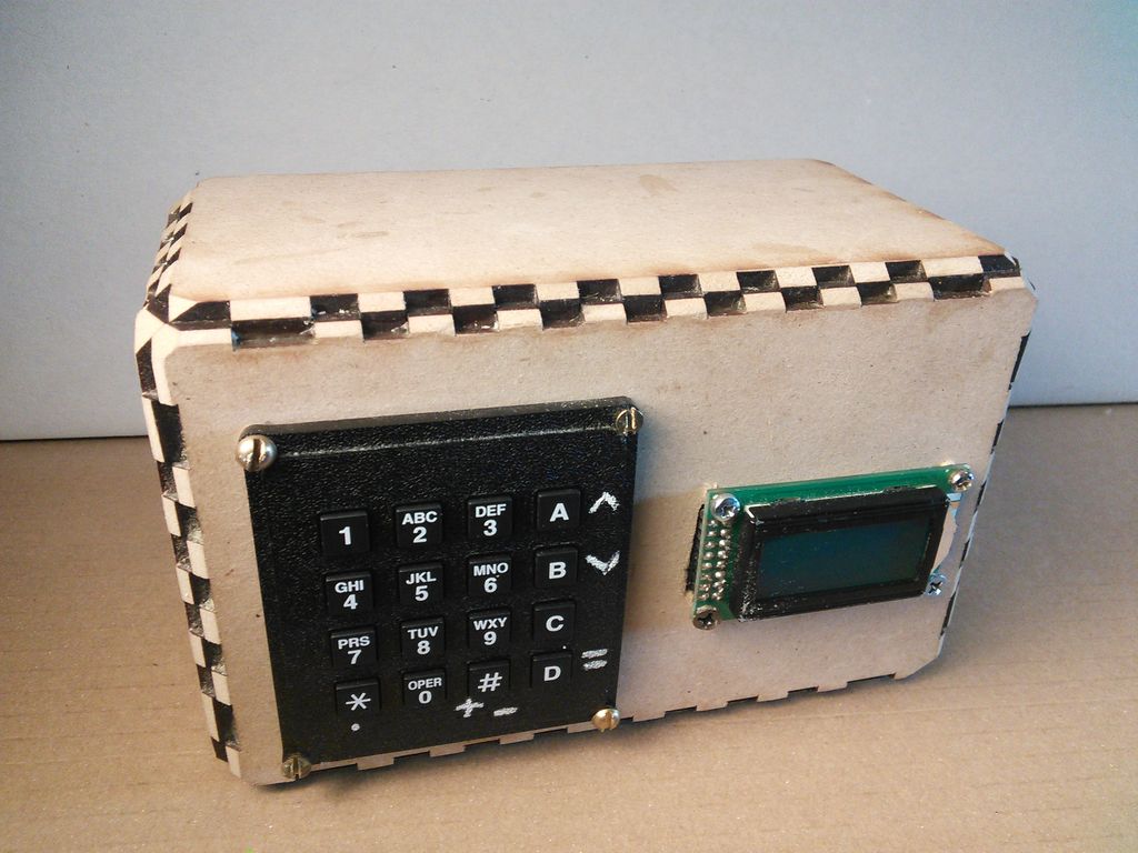
In this Instructable I will show you how to make an Arduino calculator that is just as good as any other calculator (well… sort of). Even though it’s probably not practical due to it’s size, repetitive use of the equals button (due to the lack of keys), and cost (You can probably buy a calculator that does the same thing for $2), It is really fun and adds a few skills to your inventory. Let me tell you how I got started on this project. It all starts at school where the original calculator was made by my friend/teacher Gabe. If your curious how the old version looked click here. Soon enough students began to play with it and soon broke it. I was the only student who knew how to fix it so I decided I might as well try. In the process I basically took the whole thing apart and started from scratch. I also rewrote most of the code. I learned alot, spent lots of time debugging, and added many new features. In the end it was a project definitely worth doing. The good thing is that now that I figured it out you don’t have to. Let’s get started.
Step 1: Tools and Materials
For this project we will need:
– 1/8″ MDF or other laser cuttable material such as acrylic or plywood
-Laser cutter (optional but recommended)
-Wood glue
-Male to male wires
-Many male to female wires
–8 by 2 LCD screen
–Keypad
-Drill
-Drill bits
-Disc grinder (optional)
-Switch (rocker or toggle)
-Heat shrink tubing
-Soldering iron and solder
-Screws
-USB A to B cable (cable differs between arduino models)
-Computer with arduino IDE
-Arduino (I used a duemilanove if you don’t want to spend $30 on one search it on ebay)
Step 2: Making the case
My case was laser cut (I will attach files below in PDF format) from 1/4″ MDF but that’s because I couldn’t find any 1/8″ material. The calculator edges look weird because I used the wrong thickness of material. You may be wondering why the box fits together perfectly in the picture above and that’s because that box is a completely different cutting designed for 1/4″ material. The box doesn’t include holes for the LCD or keypad due to variety. That’s where the drill comes in. Let me just clear this up one last time USE 1/8 INCH THICK MATERIAL.
 calc case.pdf2 KB
Step 3: Drilling and further assembly
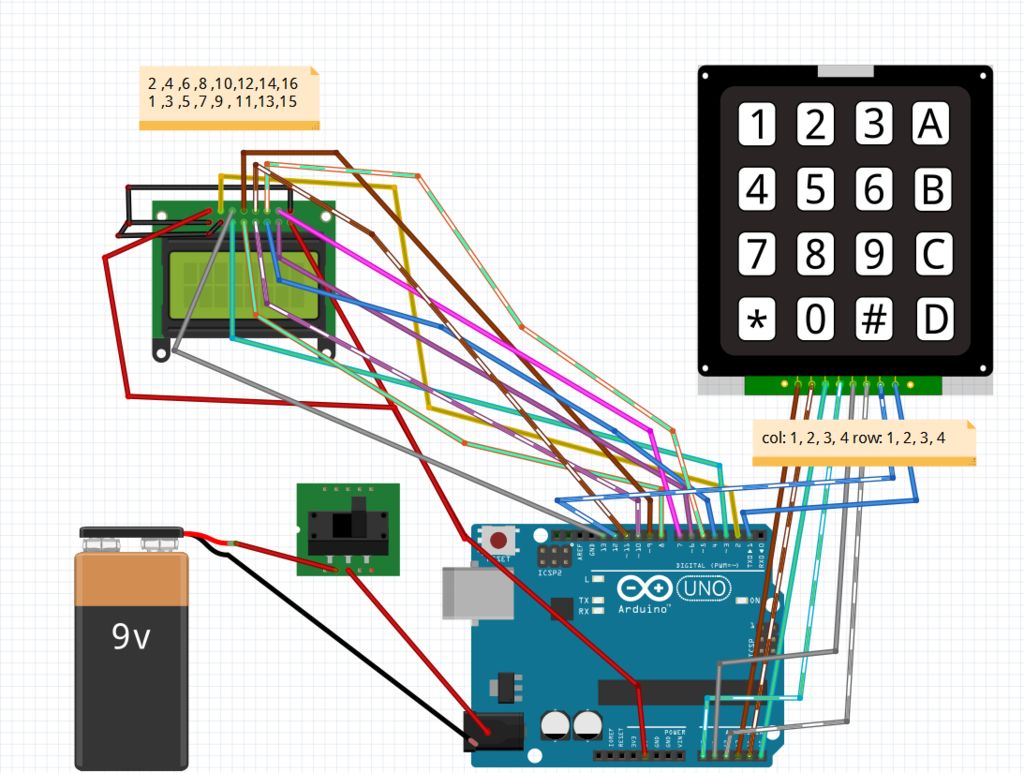
Lay down the keypad and LCD screen where you want them and use a pencils to mark where the holes are. Find a drill bit that fits the correct size and make the hole. Before screwing in the keypad or LCD holes must be made for the wires to the arduino. To do this you an either modify the laser cut or drill a few holes in a row with a wide enough drill bit and then act like a manual CNC machine pushing the drill sideways toward the other holes until you connect them by routing through. Once this is done connect the wires and to the components and screw the LCD and Keypad into place. Now use the wood glue to glue all of the cut pieces together, you might want to leave the top open for maintenance (trust me don’t glue on the top until you are done). If you want to you can use a disc grinder to sand down the edges. You might notice in my laser cut I added an access hatch on the back to make the calculator accessible if broken (Got that idea so I wouldn’t have to start over again if the calculator broke).
For more detail: Arduino Calculator
- What material thickness should be used for the case?
You must use 1/8 inch thick material like MDF, acrylic, or plywood. - Can I build this without a laser cutter?
A laser cutter is optional but recommended; you can drill holes manually if needed. - How do I route wires through the case walls?
Drill a few holes in a row with a wide bit and push the drill sideways to connect them. - When should I apply wood glue to the case?
Glue the pieces together after connecting wires, but leave the top open until you are done. - Does the provided case design include holes for components?
No, the box does not include holes for the LCD or keypad due to variety. - Why did the author rebuild the original calculator?
The original was broken by students playing with it, and the author knew how to fix it. - What features were added during the rebuild?
The author rewrote most of the code and added many new features after debugging. - Is there a way to access the internals later?
Yes, the design includes an access hatch on the back for maintenance.
