
Summary of Arduino Network relay
This article describes an Arduino-based circuit for remotely controlling electrical devices via a local network or internet. It features temperature and humidity monitoring, fault detection through an optocoupler-protected switch input (5V–12V), and supports applications like heating control and computer rebooting. Users can customize the IP address and port within the sketch to suit their network configuration.
Parts used in the Arduino Network Relay:
- Arduino
- Enc28j60 Ethernet Module
- Optocoupler
- Feedback Switch
- Temperature Sensor
- Humidity Sensor
Introduction
Some times there is a need of remote controlling electrical devices through local network or Internet. This circuit comes to cover that need.
This circuit was initially designed to remote turn on or turn off the central heating system of a building and simultaneously provides the temperature and humidity values of the room where this circuit is installed. Of course it can be used in a lot of applications such as remote reboot computers, electrical water pumps, lighting control and many more.
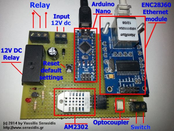
Moreover, the circuit has a feedback switch, isolated with an optocoupler (5V – 12V DC input) for protecting the Arduino pin from possible sensor overvoltage. This switch input connector can be connected to the ‘fault‘ output of your remote device to inform you when a ‘fault’ occurs on your remote device.
Remember! The voltage applied on ‘Switch input’ can be from 5V DC to 12V DC.
Change IP address and port:
– Open the NetworkRelay2_enc28j60.ino sketch to the line IPAddress ip(192, 168, 1, 240) and change the IP according to your local network. Program the Arduino with the sketch.
– (Optional) The port can be changed from the line #define ETHERNET_PORT 10000. Change the port 10000 with the port number you want.
For more detail: Arduino Network relay
- What is the primary function of this circuit?
The circuit allows remote control of electrical devices through a local network or Internet while providing room temperature and humidity values. - How do you change the IP address for the device?
Open the NetworkRelay2_enc28j60.ino sketch, locate the line with IPAddress ip(192, 168, 1, 240), and modify it to match your local network settings before programming. - Can the port number be changed?
Yes, the port can be modified by changing the value on the line #define ETHERNET_PORT 10000 to your desired port number. - What voltage range is safe for the switch input?
The voltage applied on the Switch input must be between 5V DC and 12V DC. - How does the circuit protect the Arduino pin from overvoltage?
It uses an optocoupler to isolate the feedback switch input, protecting the Arduino pin from possible sensor overvoltage. - What other applications can this circuit support besides heating control?
It can be used for remote rebooting computers, controlling electrical water pumps, lighting control, and many more. - How does the system inform the user about faults?
The switch input connector connects to the fault output of a remote device to inform the user when a fault occurs.
