Make your own dual programmer in AVRDUDE
Modified 9/16/2014
Those of you who have programmed an Arduino through the Arduino or AVR Studio IDE may have noticed the utility that is really doing the work: AVRDUDE (AVR Downloader/UploaDEr). This is a powerful program that can facilitate programming new sketches on top of a bootloader, load a brand new bootloader or chip image, capture the current firmware programmed on the chip, and set fuse bits (which can render your chip unusable without special tools if you’re not careful).
You mean I could have been doing this the whole time?
The LEDgoes USB Communicator supports both programming over serial (bootloader must be present) or via ICSP bitbang (very slow). The ICSP operation is identical to Adafruit’s FTDI Friend product. The serial programming is identical to the Arduino, except that in my case, I’d like to be able to program two ATmega chips at the same time without switching cables. What’s the best way to do this?
My original train of thought (from Mixing Logic With ISP Circuitry For Programming Firmware) involved using a switch and AND gates to decide which chip would actually get the bits. Granted, that article was really geared for SPI programming, but the concept is even more applicable to serial programming since our UART lines (TX & RX) are common among both chips on the board. Trying to program one chip without holding the other in RESET will cause a failure to write the program, as they will both try to send serial output on the same wire & confuse each other. However, the logic gates used for switching still required either manual intervention or use of a Raspberry Pi which didn’t really work out for me at the time. I thought it was going to come to me needing to get yet another microcontroller just to handle one single bit of output from AVRDUDE to control the RESET lines, which seemed really stupid. It was getting very annoying to wire up the boards two different ways to program both of the chips, though, so I still drove to find a solution.
After examining a serial port’s configuration, and seeing which pins were still available after Arduino’s serial programming application had been implemented, I decided it’d be simpler to use AVRDUDE to hold one chip in RESET while the other is programmed.
What if I don’t have LEDgoes?
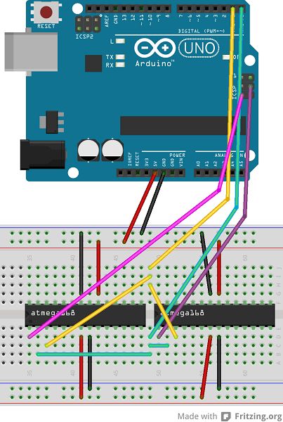
Good news! You can use an Arduino to do this as well. If you haven’t familiarized yourself with the ICSP header pins on the Arduino board, you’ll get a crash course here. The “RESET” header pin you can tap into is, obviously, electrically connected to the ATmega RESET pin, but it’s also connected to the “RST” pin (#5) on the ICSP header. AVRDUDE maps this RST signal to the “DTR” (Data Terminal Ready) serial signal coming from the FTDI USB/serial chip. This is part of the mechanism used under the hood each time you upload a sketch. However, this new AVRDUDE programmer defined below will also activate the MOSI pin on the ICSP header (#4), which is linked to the RTS signal from the FTDI chip (Request to Send). Between these two pins (RST <- DTR, and MOSI <- RTS), we can hold one chip in reset while the other one is being programmed.
One small catch: you need to take off the on-board ATmega chip if you don’t plan to use it. For folks with SMD edition Arduinos, you cannot program two external chips without making some adjustments. The code below assumes you have exclusive use of the RST line (i.e. the “RST” ICSP header used in the diagram below, or the Arduino “RESET” pin). However, the SMD chip’s reset pin is hooked up to this same RST line. Thus, if you connect an external chip to this RST line while the on-board chip is still in place, the two chips will be programmed at the same time, and that always causes problems. Usually when this happens, the chips start talking over each other loudly enough to make AVRDUDE fail. In this case, AVRDUDE passes but the program on the external chip will be all screwed up.