
Summary of Pi On The Wall – wall mounted home server
This article details the second phase of building a wall-mounted Raspberry Pi server by modifying hardware to fit a compact thermostat enclosure. The author removes non-essential ports like HDMI, audio, and camera interfaces, and cuts away specific components such as a large capacitor and USB jack supports. A custom 24-pin DIP socket is modified to create a low-profile connection between the Pi and the PiTFT display, ensuring the assembly fits within the strict 12mm depth constraint.
Parts used in the Wall-Mounted Server:
- Raspberry Pi
- PiTFT board
- Re-purposed room thermostat casing
- Solder sucker
- Solder wick
- Cutters
- Pliers
- 90 degree terminal pins
- 24-pin DIP socket
This is Part 2 of a series of blogs regarding the development of a wall-mounted server based on the Raspberry Pi, featuring WiFi and a colour touchscreen. Part 1 can be found here.
The enclosure I’m using, a re-purposed room thermostat casing, places some very tight constraints on the dimensions of the Raspberry Pi and PiTFT board.The plastic used in the case is quite sturdy, and is at least 2mm in thickness. Therefore the real inner depth of the case is about 12mm. As for the width of the Pi, we need to shave at least 4mm from the side. The Pi itself is 86mm wide, same with the PiTFT board, so we will need to find a way of making it closer to 82mm.
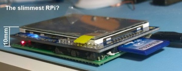
The board interconnect that comes with the PiTFT is a tall terminal connector. It is immediately ruled out for use, as it increases the depth of the assembly to well over an inch. Without using that, and bending the pins to grip the I/O on the PiTFT, the depth from SD card housing to top of the TFT is just over 20mm. Still far too much.
The main space-wasters on the Pi are easy to identify. The composite out, audio out, USB, HDMI, and the camera and display interfaces all can be removed. The tallest of these, the Composite out, measures over 11mm alone. The only one we need to use is USB, and we can add terminals to enable an off-board connector for that. All the others need to go.
The composite, audio and USB jacks were relatively easy to remove. Solder sucker & solder wick with some wiggling did the trick. The HDMI socket was another matter entirely. There were some components near the socket I didn’t want to destroy, and one of the soldered through-hole supports wouldn’t budge. Butchery was resorted to, using cutters to chip away at the metal surround and later the plastic. The connector itself is surface mount, and came off fairly easily after that. Once destroyed, the through hole-support gave in and came out with more wiggling. I apologise to all who were involved in designing the Pi for the following image.
Some PCB pads came off at the HDMI socket, but I was not concerned, as this was destructive change anyway. The camera and display interface connectors I simply cut away with pliers, again, a few pads came off.
C6 is the large silver capacitor near the micro usb socket. This is the last item in the way on the top of the board, and as you can see from the Raspberry Pi schematic, is just a smoothing capactor for the power. It can be safely removed and if needed, put off-board in seperate power circuitry. I’ve identified D17, a protection diode on the opposite side of the PCB, as we will come back to this later. The board ends up incredibly bare and on the top side it’s only a few millimeters tall.
After this I put a 90 degree set of terminal pins in the USB location so we can put the socket off-board. If we knew everything was going to work at this point the easiest thing to do would be to solder the PiTFT board directly to the GPIO pins of the PI. However, I wanted to remove the Pi from the TFT board to adjust things in future, so had to come up with a solution without using standard terminal connectors, which are too tall. I decided to try taking a DIP socket and using that, as they are only 3mm tall. The first two pins are not required, so sawing a 24-pin socket in half, inverting it for a flush fit and filing down worked exceptionally well.
For more detail: Pi On The Wall – wall mounted home server
- Why was the standard PiTFT interconnect ruled out?
The tall terminal connector increases the assembly depth to well over an inch, which exceeds the case constraints. - Which ports were removed from the Raspberry Pi board?
The composite out, audio out, HDMI, and camera and display interfaces were removed to reduce height. - How was the HDMI socket removed from the board?
Butchery was used with cutters to chip away at the metal surround and plastic before removing the surface mount connector. - What is the function of component C6 on the Raspberry Pi?
C6 is a smoothing capacitor for the power supply near the micro USB socket. - How did the author solve the issue of connecting the Pi to the TFT without using tall connectors?
A 24-pin DIP socket was sawn in half, inverted, and filed down to create a flush 3mm high connection. - What is the inner depth of the re-purposed thermostat casing?
The real inner depth of the case is about 12mm due to the 2mm thick plastic walls. - Why was the width of the Pi reduced?
The width needed to be shaved by at least 4mm to fit inside the specific constraints of the enclosure. - Can the removed capacitor C6 be replaced?
Yes, if needed, it can be put off-board in separate power circuitry.