
Summary of Pocket Photodiode Geiger Counter
This article details building a DIY Geiger counter using a BPW34 PIN photodiode to detect alpha and beta radiation, replacing costly Geiger-Mueller tubes. The compact circuit is soldered onto a protoboard within an aluminum enclosure, utilizing copper tubing and foil for noise filtering. Construction involves precise component placement, including transistors, op-amps, and various passive components, with specific shielding techniques to ensure accurate detection.
Parts used in the Pocket Photodiode Geiger Counter:
- Soldering iron and solder
- Aluminum foil
- Electrical tape
- Drill
- Step drill bit
- Hand tools
- Jumper wiring
- 3 CR1620 coin-cell batteries (or equivalent 9V)
- 2 pieces of copper tubing
- 1 BPW34 PIN photodiode
- 1 LM358 Dual Op-amp
- 1 2N3904 NPN Transistor
- 1 2N7000 Transistor
- 2 100nF Capacitor
- 1 100uF Capacitor
- 1 10nF Capacitor
- 1 20nF Capacitor
- 1 610Mohm Resistor
- 2 1.5Mohm Resistor
- 1 56kohm Resistor
- 1 150kohm Resistor
- 2 1kohm Resistor
- 1 250kohm Potentiometer
- 1 Piezo Buzzer
- 1 Toggle Switch
- 2 Crimp pins
- 1 2-pin Male Header
- 1 2-Position Housing Connector
- 1 Potentiometer Knob
- 1 8-pin IC socket
- 1 Protoboard
- 1 Fliptop Box
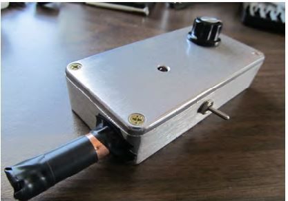
Build a DIY geiger counter that uses a PIN photodiode as a substitute for an expensive Geiger-Mueller tube. It detects alpha and beta radiation particles. The circuit is soldered onto a small protoboard and everything is placed in an aluminum enclosure. Copper tubing and a piece of aluminum foil is used to help filter out noise and RF interference.
Step 1: Required
Required tools and parts:
Soldering iron and solder Aluminum foil Electrical tape Drill Step drill bit Hand tools Jumper wiring 3 CR1620 coin-cell batteries, or any coin-cell batteries to add up to 9V 2 pieces of copper tubing available at Home Depot.
1 BPW34 PIN photodiode
1 LM358 Dual Op-amp
1 2N3904 NPN Transistor
1 2N7000 Transistor
2 100nF Capacitor
1 100uF Capacitor
1 10nF Capacitor
1 20nF Capacitor
1 610Mohm Resistor
2 1.5Mohm Resistor
1 56kohm Resistor
1 150kohm Resistor
2 1kohm Resistor
1 250kohm Potentiometer
1 Piezo Buzzer
1 Toggle Switch
2 Crimp pins
1 2-pin Male Header
1 2-Position Housing Connector
1 Potentiometer Knob
1 8-pin IC socket
1 Protoboard
1 Fliptop Box
These products are kitted at:
Step 2: Position the IC Sockets
Since there are quite a few components that need to fit onto this small protoboard. positioning of each component is important. The IC socket should be around the middle of the board since the pins need to be accessed as you solder. Make sure the notch of the socket is positioned correctly as you want the IC to be placed.
Follow the schematic paying close attention to the pinouts of the transistors and dual op-amp IC.
As you can see from the schematic, pins 1 and 6 are tied together. Soldering the two pins from underneath the board is the best way to have a clean connection and save space at the same time. This technique will be used throughout the build to keep the entire circuit compact.
Step 3: Place Resistors
Solder each resistor so that they only take up 2 solder holes. The connections are made underneath so make sure you do not short any of the components by soldering its own leads together.
Step 4: Capacitor
Place 20nF Capacitor
This capacitor is non-polarized. It connects to ground, which I am using as the bus on the protoboard.
Place 10nF Capacitor:
This capacitor goes from pin 5 to pin 7. It is non-polarized.
Step 5: Light Shield Section
The Light Shield section of the schematic is going to be placed in a copper tube to help block out any electromagnetic interference and light coming into the photodiode. Soldering the components in a tube-like shape ensures a snug fit into the copper tube. Start by placing the photodiode on top of the 2N7000 MOSFET and soldering the gate (pin 2) to the anode of the photodiode (without the notch).
Step 6: Solder Resistors and Capacitors
1.5Mohm Resistor to Photodiode
The cathode of the photodiode (with a notch) is connected to the 1.5Mohm resistor.
56kohm Resistor
Solder one end of the 56kohm resistor to the drain of the 2N7000 (pin 1), and the other end to the 1.5Mohm resistor.
100nF Capacitor
Solder the 100nF capacitor to the cathode of the photodiode and leave the other end unconnected.
Step 7: 10Mohm Resistor
Solder on end of the 10Mohm resistor to the source of the 2N7000 (pin 3), and the other end to the gate of the 2N7000 (pin 2). Add a jumper wire to the source (this will connect to ground), and another jumper wire to the connection between the 1.5Mohm and 56kohm resistors (this will connect to the emitter of the 2N3904 transistor).
Add one more jumper wire to the drain of the 2N7000 (pin 1). This will connect to pin 3 of the dual op-amp IC. To make sure these solder connections aren’t accidentally shorted, place electrical tape around each lead.
Step 8: Solder the Light Shield section to the Protoboard
There will be 4 connections made from the Light Shield section to the protoboard: Two connections go to ground, one connection goes to pin 3 of the dual op-amp, one connection goes to the emitter of the 2N3904 transistor.
For more detail: Pocket Photodiode Geiger Counter
- What components are used to filter out noise and RF interference?
Copper tubing and a piece of aluminum foil are used to help filter out noise and RF interference. - Can this device detect alpha and beta radiation particles?
Yes, the circuit detects alpha and beta radiation particles using a PIN photodiode as a substitute for an expensive Geiger-Mueller tube. - How should the IC socket be positioned on the board?
The IC socket should be placed around the middle of the board so that the pins can be accessed while soldering. - What is the best way to connect pins 1 and 6 of the dual op-amp IC?
Soldering the two pins from underneath the board is the best way to have a clean connection and save space. - Which capacitor connects to ground in the Light Shield section?
The 20nF Capacitor is non-polarized and connects to ground, which serves as the bus on the protoboard. - Where does the 100nF capacitor connect in the assembly?
The 100nF capacitor is soldered to the cathode of the photodiode, leaving the other end unconnected. - How many connections are made from the Light Shield section to the protoboard?
There are four connections made: two go to ground, one goes to pin 3 of the dual op-amp, and one goes to the emitter of the 2N3904 transistor. - What power source is required for the project?
The project requires 3 CR1620 coin-cell batteries or any coin-cell batteries arranged to add up to 9V. - Why is electrical tape applied during the build process?
Electrical tape is placed around each lead to ensure solder connections are not accidentally shorted.