
Summary of ‘Knock Back’ – A Knock Echoing Arduino
This Arduino project records user knocks via a piezo sensor and replays the pattern using an LED and buzzer. It utilizes arrays to store timing data and triggers playback after a set silence period. The system can be expanded with motors or by reusing the piezo as an output.
Parts used in the Knock Echoing Arduino:
- Arduino UNO or compatible board
- LED
- 220R resistor
- Piezo sensor
- 1M pull-down resistor
- Piezo buzzer
- Breadboard
- Wires
This is a simple Arduino sketch that was originally designed to experiment with arrays and the built-in timing functionality. I based it on the tutorial sample code http://www.arduino.cc/en/Tutorial/Knock
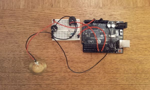
The system consists of a piezo sensor connected to an analog pin that listens for a knock from the user. The Arduino then stores the time the knock occurred in an array. After a predefined time without further knocks occurring, the Arduino will ‘play back’ the knocks on a buzzer and LED in time to the original knocking pattern.
The device could be expanded to include a stepper motor or similar suitable output that would recreate the knocks exactly, just replace the output buzzer.
You could also use the piezo input sensor as the output buzzer by altering the code.
Step 1: Materials
You will need:
1. An Arduino UNO or compatible board.
2. An LED and appropriate resistor (I used 220R).
3. A piezo sensor.
4. A 1M pull-down resistor.
5. A piezo buzzer or alternative output device (see page one notes).
6. A breadboard and wires.
Step 2: Assemble
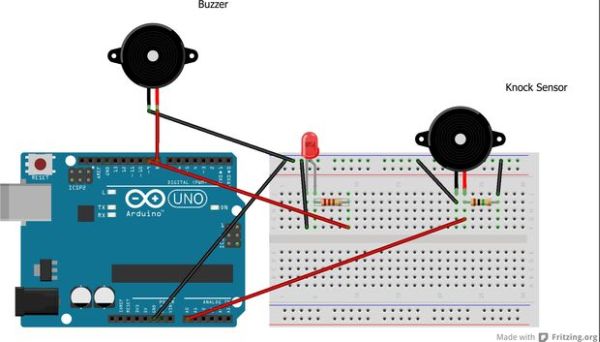
The configuration of the device is fairly simple.
1. Connect the LED to pin 9 (via the resistor) and GND.
2. Connect the output buzzer to pin 8 and GND.
3. Connect the knock senzor to analog pin 0 AND GND.
4. Connect your 1M resistor to the positive wire of the knock sensor and GND. This is used as a pull-down resistor.
Note: Be sure to check that my resistor recommendations are correct for the components you are using, including the lack of resistors on the two piezo buzzers.
Step 3: The Sketch
Upload the following to your Arduino.
/* Echoing Knock Sensor
This sketch reads a piezo element to detect a knocking sound.
It reads an analog pin and compares the result to a set threshold.
If the result is greater than the threshold, it stores the value of millis() to an array.
Following a defined period without additional knocks, the knocks are replayed by the device.
Created by Dan Nicholson <http://dannicholson.co.uk>
Based on “Knock Sensor” created 25 Mar 2007 by David Cuartielles <http://www.0j0.org> modified 30 Aug 2011 by Tom Igoe
*/
// these constants won’t change:
const int ledPin = 9; // led connected to digital pin
const int buzzer = 8; // output buzzer connected to digital pin.
const int knockSensor = A0; // the piezo is connected to analog pin 0
const int threshold = 100; // threshold value to decide when the detected sound is a knock or not
const int arraySize = 20; // Size of knock array (you can remove this in the functions and use sizeof() if you prefer)
const int replayWait = 2000; // Number of milliseconds to wait before replaying knock pattern
// these variables will change:
int sensorReading = 0; // variable to store the value read from the sensor pin
unsigned long knocks[arraySize]; // Knock ‘buffer’ – stores timing of each knock ready for replaying.
int knockPos = 0; // Current position within knocks array
unsigned long lastKnock = false; // Time of last knock
void setup() {
pinMode(ledPin, OUTPUT); // declare the ledPin as as OUTPUT
pinMode(buzzer, OUTPUT); // declare buzzer pin as OUTPUT
Serial.begin(9600); // use the serial port
}
void loop() {
sensorReading = analogRead(knockSensor); // read the sensor
if (lastKnock && (lastKnock + replayWait) < millis()) replayKnocks(); // Replay knocks if last knock was older than the defined wait time
else if (sensorReading >= threshold) handleKnock(sensorReading); // If knock detected, handle
delay(30);
}
void handleKnock(int reading)
{
lastKnock = millis();
if (knockPos < arraySize)
{
knocks[knockPos++] = lastKnock; // Store timing and increment position variable
flash(false);
// Debug output
Serial.print(“Knock: “);
Serial.println(reading);
}
else
{
Serial.println(“Buffer full”);
}
}
void flash(boolean buzz)
{
digitalWrite(ledPin, HIGH); // turn the LED on (HIGH is the voltage level)
if (buzz) tone(buzzer, 1000);
delay(50);
digitalWrite(ledPin, LOW); // turn the LED off (LOW is the voltage level)
if (buzz) noTone(buzzer);
}
void replayKnocks()
{
int i;
lastKnock = false;
Serial.println(“Replaying”);
for (i = 0; i < knockPos; i = i + 1)
{
int prev = i-1;
if(prev < 0) prev = 0;
unsigned long d = (knocks[i] – knocks[prev]);
if (d > 50) d = d-50;
delay(d);
Serial.println(i);
flash(true);
}
knockPos = 0; // reset pointer;
}
For more detail: ‘Knock Back’ – A Knock Echoing Arduino
- How does the device detect a knock?
The system reads an analog pin connected to a piezo element and compares the result to a threshold value of 100. - What happens when the last knock is older than the wait time?
The Arduino triggers the replayKnocks function to play back the stored knocking pattern. - Can the piezo sensor be used as an output device?
Yes, you can use the piezo input sensor as the output buzzer by altering the code. - Which pins are used for the LED and buzzer?
The LED connects to digital pin 9 and the output buzzer connects to digital pin 8. - What is the purpose of the 1M resistor?
The 1M resistor acts as a pull-down resistor connected between the positive wire of the knock sensor and GND. - How long does the system wait before replaying knocks?
The device waits for 2000 milliseconds without further knocks before initiating the replay sequence. - Can this project be expanded to include other outputs?
Yes, it could be expanded to include a stepper motor or similar suitable output that would recreate the knocks exactly. - What array size is defined in the sketch?
The constant arraySize is set to 20 to store the timing of each knock ready for replaying.