Summary of Laser Triggered Countdown
This Arduino project creates a laser tripwire alarm that triggers a countdown sequence on LEDs when the laser beam is interrupted. Designed for beginners, it uses an LDR and laser to detect breaks in the light path, then activates red, orange, and green LEDs to signal a countdown before turning green for "GO." The system requires calibration to distinguish laser light from ambient light, ensuring reliable triggering only when the beam is blocked.
Parts used in the Laser Triggered Countdown:
- Arduino Uno (or similar)
- Breadboard
- LEDs (3x Red, 2x Orange, and 1 Green)
- 3x 150 Ohm Resistors (or similar)
- 1x 10K Resistor
- LDR (Light dependent resistor)
- Laser
- Jumper wires for breadboard
- Electrical tape
- Power Supply for Arduino (USB or battery)
- Arduino Prototype shield (optional)
This is a simple arduino based project that consists of a laser tripwire that, when triggered, will begin a countdown sequence on red, orange and green LEDs. I designed this to be an easy project for someone learning how arduinos work (like me).
This is my first instructable so please bare with me 🙂
(I’ll apologies in advance the picture quality, my phone’s camera isn’t too great)
Let’s Go!
Step 1: Materials
Materials needed for this project:
– Arduino Uno (or similar)
– Breadboard
– LEDs (3x Red, 2x Orange, and 1 Green)
– 3x 150 Ohm Resistors (or similar)
– 1x 10K Resistor
– LDR (Light dependent resistor)
– Laser
– Jumper wires for breadboard
– Electrical tape
– Power Supply for Arduino (USB or battery)
– Arduino Prototype shield (optional)
Step 2: Connecting the components
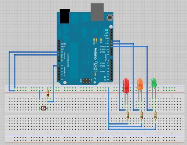
Connect all the components using the diagram as a guide.
The ldr will have one leg hooked up to the arduino’s 5volt and the other connected to the arduino’s ground through the 10k resistor. The ldr will also have one leg connected to analog 0.
All the LEDs are connecting in parallel with their positive terminals connected to the arduino (Red – digital pin 13, Orange – digital pin 12 and green – digital pin 11) and their negative terminals connected to ground through a 150 ohm resistor.
I hope the diagram (Made with Fritzing) explains this better than I have.
Step 3: Programming
First of all we need to calibrate the laser to its surroundings.
Take the now completed circuit to the location that this will be used. Connect the arduino to a laptop or computer and open the arduino software installed on it.
Copy + paste this sketch into the window:
// Laser Calibration
void setup()
{
Serial.begin(9600);
}
void loop()
{
Serial.println(analogRead(0));
}
Upload this to your arduino and open the serial window.
With the serial window open point your laser so it shines directly upon the ldr.
You will notice that the numbers in the serial window rise up to around 900ish. (if this doesn’t happen go back to step 2 and check that all your wiring is correct)
Note down the average number seen and take 50 away from it (mine was around 950 so I ended up with 900)
This number stops the ldr from reacting to the atmospheric light and just the light emitted from the laser.
Now copy and paste the following sketch into the arduino window:
// LASAR TRIGGERED COUNTDOWN
#define Red 13
#define Orange 12
#define Green 11
void setup()
{
pinMode(Red, OUTPUT);
pinMode(Orange, OUTPUT);
pinMode(Green, OUTPUT);
}
void loop()
{
if(analogRead(0) < 900) // Enter the value you got when calibrating here, mine was 900
{
digitalWrite(Red, HIGH); // 5
delay (950);
digitalWrite(Red, LOW);
delay (50);
digitalWrite(Red, HIGH); // 4
delay (950);
digitalWrite(Red, LOW);
delay (50);
digitalWrite(Red, HIGH); // 3
delay (950);
digitalWrite(Red, LOW);
delay (50);
digitalWrite(Red, HIGH); // 2
delay (950);
digitalWrite(Red, LOW);
delay (50);
digitalWrite(Orange, HIGH); // 1
delay (950);
digitalWrite(Orange, LOW);
delay (50);
digitalWrite(Green, HIGH); // GO!
delay (5000);
digitalWrite(Green, LOW);
}
else
{
digitalWrite(Red, LOW);
digitalWrite(Orange, LOW);
digitalWrite(Green, LOW);
}
}
Find the line *if(analogRead(0) < 900)* and replace 900 with your calibration number
For more detail: Laser Triggered Countdown
- What components are required for this project?
You need an Arduino Uno, breadboard, LEDs, resistors, an LDR, a laser, jumper wires, electrical tape, and a power supply. - How do you calibrate the laser sensor?
Upload the calibration sketch, open the serial window, shine the laser on the LDR, note the average reading around 900, and subtract 50. - Can I use a different microcontroller than the Arduino Uno?
Yes, the article states you can use an Arduino Uno or a similar board. - Does the code require manual editing after uploading?
Yes, you must replace the default calibration number in the if statement with your specific calibrated value. - How are the LEDs connected to the Arduino pins?
Red connects to digital pin 13, Orange to digital pin 12, and Green to digital pin 11. - What happens when the laser beam is broken?
The circuit detects the drop in analog reading and initiates a countdown sequence using the red, orange, and green LEDs. - Why is a 10K resistor used with the LDR?
The 10K resistor connects the LDR leg to ground to form a voltage divider circuit with the analog input. - How long does the final green light stay on?
The green LED stays on for 5000 milliseconds (5 seconds) after the countdown completes.