
Summary of LCD Temperature Shield Assembly Instuctions
This article provides assembly instructions for an LCD Temperature Shield with a buzzer. The guide covers preparing tools, soldering components like the buzzer and contrast potentiometer, installing push buttons, and adding a header for the LCD. It notes that production boards may differ slightly from the prototype photos shown but that the assembly steps remain similar.
Parts used in the LCD Temperature Shield:
- Buzzer
- 10K Pot (Contrast)
- Optional 10K Pot (Brightness Control)
- 2 Push Buttons (Tact-Switches)
- LCD Header
- 10K Pull-up Resistor
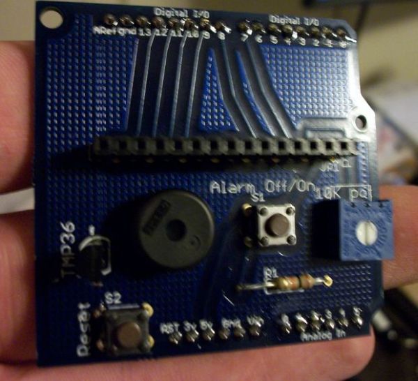
These are assembly instructions for the LCD Temperate Shield with buzzer that i am going to be selling soon. Please note, all the photos are my own, but are of one of my Prototype stage boards, and are subject to change, the production boards WILL look different and may have slightly altered layout, but the directions are similar, and once i get production going, i’ll update the photos.
Link to my site with the code and more information regarding the “kit”: http://tinyurl.com/2fksv8h
Step 1: Prepare your tools and your parts
Make sure you have all your parts per the bil of materials(BOM) and all the tools, for some recomendats i’ll like to some ladyada guides. This also won’t instruct you “how to solder” per say, but i’ll link to some guides for that as well if your new at that. But i’m not going to re-write the book if its already written.
See image notes
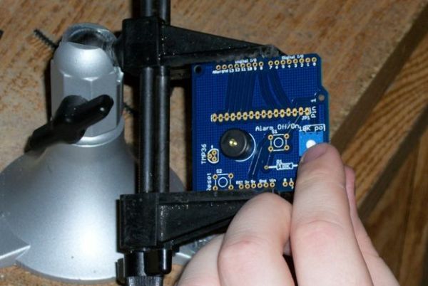
Step 2: Place your Board in a vise or something similar to hold it
Place your Board in a vise or something similar to hold it
Step 3: Place the Buzzer
Place the buzzer in the holes marked “Buzzer” The polarity Does not matter for this part
NOTE: on this particular proto run i didn’t have the right spacing on the buzzer holes, so the buzzer doesn’t sit flush on the board, you will want to make yours flush(as the holes have since been fixed)
I recommend flaring the leads out to help hold the part in place for soldering, as seen in the second photo
Now Solder the pins and then clip the leads
Step 4: Place the Contrast Pot
Place the Contrast Pot in the whole marked 10K Pot(Contrast)
Again, the orientation doesn’t mater with this part, and just solder and clip the leads
NEW: in the latest revision i also added a spot that you can your own pot to control the brightness, the pot isn’t included and by default is “jumpered” so its set to full brightness, but you can cut this jumper and soldering in a pot(10K or similar) Pictures coming Soon
Step 5: Place the 2 Push Butons
Next place the 2 Push Button “Tact-Switchs”, the can only fit in easily 2 ways, make sure the leads are on the sides as shown, and the switchs should “snap” in to hold them. But you shouldn’t have to bend the leads to fit them in the hole, it should line up easily.
Solder the pins(4 on each button) and you can trim these leads if you want, i like all my leads short, so i did
Step 6: Placing the Header for the LCD
Placing the Header for the LCD, you could also solder the pins from the LCD directly to the board, but for my taste, i don’t like to tie the LCD to one project, this makes it so if the LCD went bad you can replace it easily, or if you need to “borrow” the LCD for something you can do that easily as well.
Please note, i used the locking header foot print from Sparkfun here. so the header takes a little bit of force to get in, but afterwords it stays on its own for soldering.
Step 7: Placing in the 10K Pull-up Resistor
Placing in the 10K Pull-up Resistor for the alarm On/Off switch
For more detail: LCD Temperature Shield Assembly Instuctions
- Does the polarity matter when placing the buzzer?
No, the polarity does not matter for the buzzer part. - Can I solder the LCD pins directly to the board instead of using a header?
Yes, you can solder the pins from the LCD directly to the board, though a header is recommended for easier replacement. - How do I control the brightness on the latest revision of the board?
You can cut the default jumper and solder in your own 10K pot or similar to control brightness. - What should I do if the buzzer does not sit flush on the board?
You should ensure the holes are fixed so the buzzer sits flush, as spacing issues were present only in the specific proto run mentioned. - Do I need to bend the leads of the push buttons to fit them in?
No, the switches should line up easily without bending the leads if inserted correctly. - Why is a locking header footprint used for the LCD connection?
The locking header footprint helps the header stay on its own for soldering after being forced into place. - Are the assembly directions valid for the final production boards?
Yes, while the layout may look different, the directions are similar once production begins. - Where can I find guides on how to solder?
The author links to external guides for those new at soldering rather than rewriting the instructions within this text.
