
Summary of 3D Printed Arduino Controlled Eggbot/Spherepot
This project documents building a mostly 3D printed SphereBot that writes on ping pong balls by combining Glasswalker's Thingiverse 3D parts with Pleasant Software's Arduino electronics. The author printed parts, substituted wooden side pieces, assembled a spring-loaded bearing and stepper-driven pen arm, and wired Arduino with A4983 drivers to control two stepper motors for ball rotation and pen movement.
Parts used in the SphereBot:
- Foot threaded rod
- Bolts that fit the threaded rod
- Sheet of thin craft wood (optional if not 3D printing the sides)
- Sharpie
- Hobby King 5V stepper motor
- Arduino Uno
- Breadboard
- 2x Pololu A4983 stepper motor drivers
- 2x CanaKit stepper motors
- Jumper wires
- 12V DC power supply
- Skateboard bearing
- Computer with Arduino firmware
- USB cable
- Super glue
- Nerf darts (for pen holder)
- Ping pong balls (or eggs)
- M3 machine bolts, washers and nuts
First off this project was a combination of of two great online resources. I had been looking into building an eggbot for a while and since I had a lot of ping pong balls on hand after one of my other videos the time was right for making my SphereBot that could write on ping pong balls. After doing some research online I found that there were already some brilliant designs out there.
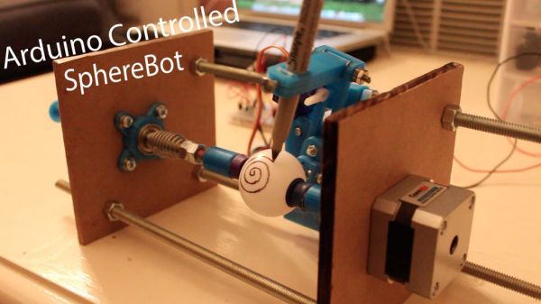
The 3D printed design came from Glasswalker’s page on thingverse
(http://www.thingiverse.com/thing:20398) and the Arduino schematic and setup came from a page on Pleasant Software’s blog (http://pleasantsoftware.com/developer/3d/spherebot/). I simply put these two designs and will document my building experience of a (mostly) 3D printed SphereBot in this instructable.
Step 1: Materials
This is what I used to build the SphereBot. I substituted wood in for the two side pieces but those parts can also be 3D printed as well. Sorry I forgot to stage a nice materials picture at the beginning…
Materials:
– foot threaded rod
– Bolts that fit the threaded rod
– A sheet of thin craft wood (if you aren’t 3D printing the sides)
– Sharpie
– Hobby King 5v stepper motor
– Ardunio uno
– Bread Board
– 2x Polulu A4983 stepper motor drivers
– 2x CanaKit stepper motors (http://www.amazon.com/dp/B004G51AZ4)
– Jumper wires
– 12V DC power supply
– Skateboard Bearing
– Computer with arduino firmware
– USB cable (to connect the arduino to the computer)
– Super glue
– Nerf Darts
-Ping Pong Balls (or eggs)
– M3 machine bolts, washers and nuts
– A Never Give Up Attitude!
– Dremel (to cut the threaded rod)
– Drill (if you use wooden side pieces)
Step 2: 3D Printing the Parts
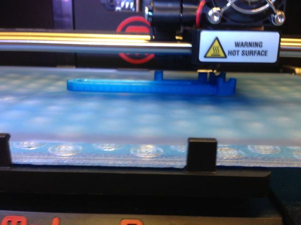
Once you download the files from Glasswalkers thingverse: (http://www.thingiverse.com/thing:20398) It is just a matter of configuring your printer settings and fabricating the parts. I used a replicator 2 and blue PLA. However settings for 3D printers vary a lot across the board even for the same model so do some experimenting before you print all of the parts. For the record these are the settings that I used.
I used makerware medium settings as follows:
-infill: 15%
-Layer height: .25
-Number of shells: 1
-Feed rate: 80
-Travel feed rate: 150
-Print temperature: 230
Step 3: Hardware Assembly
The first step is cutting the threaded rod. I cut mine into three foot long sections and then used the left overs for the part that connects to the nerf dart. Once the threaded rod was cut I assembled the pen arm that holds the stepper motor and attached it to the middle plate for the stepper motor. Then I centered the wooden sides around the pen arm. Finally I glued in the skateboard bearing in place and added the spring to keep pressure on the ping pong balls. Overall the assembly is pretty straight forward once you have the parts from the 3D printer. The most important thing to to make sure that the stepper motor that will turn the ping pong ball is centered with the spring loaded piece of the threaded rod that rests on the skateboard bearing so it can turn freely with the stepper motor (if you are using 3D printed sies this isn’t really a problem…).
Step 4: Configuring The Arduino
This circuit diagram comes directly from Pleasant Software’s blog (http://pleasantsoftware.com/developer/3d/spherebot/). I had to do some experimenting to figure out which wires were which on my stepper motors but there are plenty of tutorials for how to do that online. On my bread board there is a third motor driver that is not being used (I forgot to remove it for the picture). Anyway if you follow the blog this part should be pretty straight forward. Just make sure that you have a 12V DC power supply connected to the positive and negative rails.
For more detail: 3D Printed Arduino Controlled Eggbot/Spherepot
- What 3D files were used for the SphereBot?
The 3D printed design came from Glasswalker's Thingiverse page thing:20398. - Where did the Arduino schematic and setup originate?
The Arduino schematic and setup came from Pleasant Software's blog page on SphereBot. - Can wooden side pieces be used instead of 3D printed sides?
Yes, the author substituted thin craft wood for the two side pieces but they can also be 3D printed. - What stepper motor drivers are used in the project?
The project uses Pololu A4983 stepper motor drivers. - What power supply is required?
A 12V DC power supply is required and should be connected to the positive and negative rails on the breadboard. - How is the ping pong ball held and allowed to rotate?
A skateboard bearing and a spring-loaded threaded rod piece press against the ball while a centered stepper motor turns it. - What printing settings did the author use?
The author used MakerWare medium settings: 15% infill, 0.25 mm layer height, 1 shell, 80 feed rate, 150 travel feed rate, and 230 print temperature. - Are there additional motor drivers shown on the breadboard?
Yes, the author notes a third motor driver on the breadboard that is not being used in the pictured setup.
