Summary of 3D Printed Spirometer
This article details the design and construction of a low-cost, 3D-printed DIY spirometer. Using an ESP32 microcontroller and a pressure sensor, the device measures airflow to calculate FEV1 and FEVC metrics. It features a modular design separating the reusable electronics from disposable blow tubes to enhance hygiene. The system connects via Wi-Fi to a Blynk app for data visualization and storage, offering an affordable alternative to clinical equipment for personal lung function monitoring.
Parts used in the 3D Printed Spirometer:
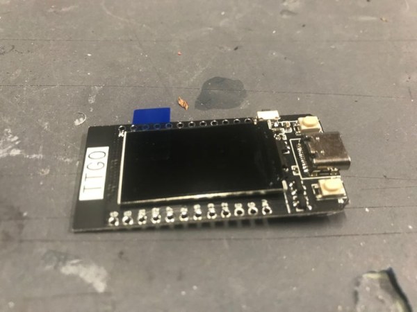
- TTGO T-Display ESP32 CP2104 WiFi bluetooth Module with 1.14 Inch LCD
- SDP816-125PA Pressure Sensor (CMOSens, 125 Pa, Analogue, Differential)
- Lipo Battery (600mah)
- On/Off Switch (Pushbutton Toggle Switch)
- M3 screws (20 mm length)
- Heat-set M3x4x5mm inserts
- Plastic aquarium tubing
- PLA filament for 3D printing
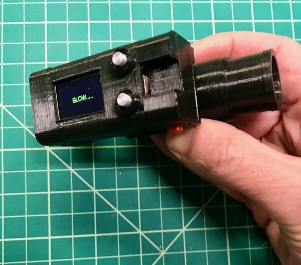
Spirometers are the classical instrument to perform the parsing of air as it is blown out of your mouth. They consist of a tube that you blow into that records the volume and speed of one breath which are then compared to a set of normal values based on height, wt and sex and are used to follow lung function. The instrument I designed, although tested for accuracy with a flowmeter is not in any way a certified medical device, but in a pinch it certainly could pass for one–giving relative reproducible and accurate accounts of the standard FEV1, FEVC and graphs of volume output and speed over time. I designed it so that the electronics with the expensive tethered sensor were confined to one piece and the easily disposable blow tube with associated virus laden channels was in another. This appears to be one of the drawbacks of standard machines used clinically — replaceable cardboard mouthpieces don’t really eliminate all risks when viruses are airborne and you’re asked to blow long and hard into a very expensive apparatus. The cost of the device is under $40 and anyone with a 3D printer can turn out as many as they want. The software Wifi tethers it to a Blynk app on your smartphone for visualization and allows you to download any data you want.
Step 1: Buy Stuff
Essentially we are building an analog sensor with a great screen/microcontroller combo. The importance is in choosing the right sensor. Several other designs for these devices have used sensors that lack the sensitivity necessary to provide the data to compute these breathing elements. The ESP32 has well known issues with nonlinearity of its ADC but this doesn’t seem to be significant in the range of this unit.
1. TTGO T-Display ESP32 CP2104 WiFi bluetooth Module 1.14 Inch LCD Development Board $8 Bangood
2. SDP816-125PA Pressure Sensor, CMOSens®, 125 Pa, Analogue, Differential $30 Newark, Digikey
3. Lipo Battery — 600mah $2
4. On/Off Switch — On-Off Power Button / Pushbutton Toggle Switch Adafruit
Step 2: 3D Print
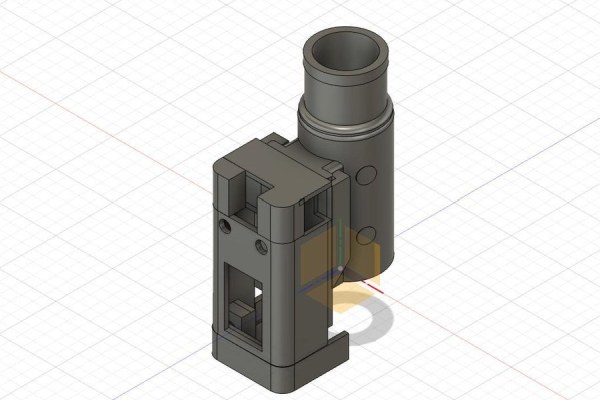
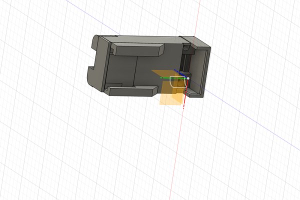
Fusion 360 was used to design the two nesting elements of the Spirometer. The Venturi tube (blow tube) has a variety of designs. To use the Bernoulli equation for the calculation of flow you must have some reduction in volume of flow in the measuring tube. This principle is used in a variety of flow sensors for all kinds of laminar flow fluids. The dimensions I used in the Venturi tube were from no particular source but they just seemed to work. The sensor uses the differential pressure across the narrow and wide tube areas to calculate flow volume. I wanted the sensor to be able to easily and reversibly engage the Venturi tube for quick change and removal so I designed the pressure sensor tubes to lead out of the model and end at its base where they would engage the tips of the sensor tube heads. There is a high/low polarity to the sensor that has to be maintained from the high/low pressure areas of the Venturi tube. The high pressure is in the straight section and the low pressure is over the curve of the restriction–just like over an airplane wing. The body of the Spirometer is carefully designed to provide screw mounts to hold the sensor in place with M3 (20 mm) screws. These are placed in heat-set M3x4x5mm inserts. The remainder of the design provides for the anchoring of the TTGO in a slot at the bottom and a window for the screen. The button and button cover are both printed twice and allow for threw-case access to the the two buttons on the TTGO board. The cover is the last piece to print and is designed to give access for the power/charging plug to the top of the TTGO board. All pieces are printed in PLA with no supports.
Step 3: Wire It
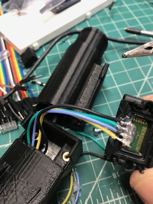
There is not much to the wiring of the sensor and the ESP32. The sensor has four leads and you should download the data sheet for the sensor just to make sure you have the leads correct: http://www.farnell.com/datasheets/2611777.pdf The power goes to the 3.3 Volt output of the ESP32 and the ground and OCS are both connected to ground. The analog output of the sensor is connected to pin 33 on the ESP. Since these connections snake through a narrow opening in the shell don’t connect them prior to the assembly of the unit. The Lipo battery fits posterior in the case so get one that is appropriately sized for the mAh. The TTGO has a charging circuit with a tiny JST connector on the back. Connect the battery to this with the on/off switch breaking the pos line.
Step 4: Assembly
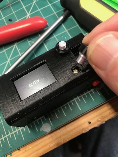
Post 3D printing modification is done to the blow tube. Two sections of plastic aquarium tubing are fitted into the bottom holes of the unit as far as they will go and then trimmed flush with clippers. This provides an elastic opening for the sensor tube openings to easily mate with. The main unit requires the installation of heat set brass inserts into the two holes in the frame. The sensor mounting holes have to be enlarged slightly for the 3mm (20 mm length ) screws with an appropriate sized bit. Mount the sensor with two screws and finish the electrical connections to the TTGO board. Connect and mount the on/off switch with superglue. Use the one from Adafruit as the case is designed to hold it exactly. The two buttons are mounted to the case with superglue. Make sure the buttons on the TTGO board line up underneath the openings. The button is installed followed by the button housing which is superglued. Make sure you don’t glue the button to its housing it must move within it freely. To stabilize the TTGO upper section place small dabs of hot glue on either shoulder to hold it in place. The battery goes posterior to the board. Finish off the assembly by supergluing the top on. There should be easy access to the USB-C connector for programming and battery charging.
Step 5: Programming
The software for this instrument takes in the analog value from the sensor changes its value to volts and uses the formula from the sensor data sheet to convert it into Pascals of pressure. From this it uses Bernoullis formula to determine the vol/sec and mass/sec of air going through the tube. It then analyzes this into individual breaths and remembers the values in several data arrays and presents the data on the built in screen and finally calls the Blynk server and uploads it to your phone. The data is only remembered until you take another breath. The clinical use of a spirometer is commonly done by asking the patient to take as big a breath as possible and blow it out for as long and hard as they can. Commonly used algorithms based on height, weight and sex are then described as normal or abnormal. Different arrangements of this data are also presented ie FEV1/FEVC –total volume divided by volume in the first second. All the parameters are presented on the Spirometers screen as well as a small graph of your effort in vol over time. When data has been uploaded to Wifi the screen returns to “Blow”. All data is lost after the power is shut down.
The first section of the code requires you to input your Blynk token. The next requires Wifi password and network name. Float area_1 is the area in sq m of the spirometer tube prior to narrowing and Float area_2 is the area in cross section directly at the narrowing. Change these if you want to redesign the tube. Vol[] and volSec[] are the two arrays that hold volume increase over time and speed of air movement. The loop function starts with calculating breathing rates. The next section reads the sensor and calculates pressure. The following if statement tries to figure out if you are done with your blow–more difficult than you think, often the pressure drops suddenly for a millisecond right in the middle of the blow. The next section calculates mass flow based on the pressure. If a new breath is detected all data is frozen and parameters calculated and sent to screen, followed by a graphing function and finally a Blynk call to upload the data. If no Blynk connection is detected it will return to “Blow”.
Step 6: Using It
Is this instrument reasonably accurate for what it purports to do? I used a calibrated flow meter connected to a source of air passed through a 3D printed laminar air chamber attached to the Spirometer and it accurately predicted within reason air flow from 5 lit/min to 20 lit/min. My resting tidal volume on the machine is about 500cc and very reproducible. With any clinical testing you have to keep in mind what is reasonable in terms of information benefit received versus effort … you can weigh yourself to the nearest gram but to what benefit? Considering the variability inherent in volitional testing effort toward the outcome it may be adequate for most clinical situations. The other concern is some people with huge lung capacity may top off the upper sensor limit. I was unable to do this but it’s possible, but these people are not likely to have lung problems…
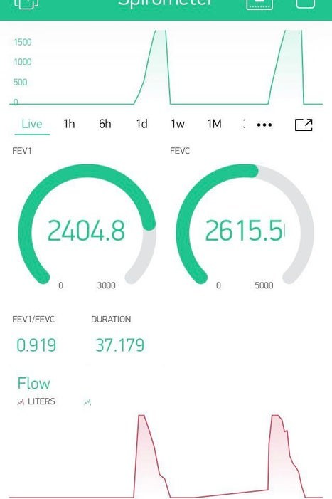
The first screen presents FEV1 and FEVC. The next data screen presents Duration of blow, FEV1/FEVC ratio and MaxFlow in Lit/Sec. I maxed it out with two screens detailing Vol over time and Lit/sec over time. The dials mock up FEV1 and FEVC and the meters print duration and FEV1/FEVC. But for those of you familiar with Blynk know you can do this any way you want on the phone app and download the data to your email with a touch.
The buttons on the side of the instrument are broken-out in case you want to program them for activating the machine with a breath or to vary the screen output or to change the Blynk connection if you want to use it offline. The buttons pull pins 0 and 35 low so just write this into the program. COVID has purportedly left many with lingering lung issues and this device may be helpful in those countries where access to expensive medical equipment may be limited. You can print and assemble this in a couple hours and print safe replacement contaminated sections of the device for nothing.
Source: 3D Printed Spirometer
- How does the device calculate air flow volume?
The device uses the Bernoulli equation by measuring differential pressure across narrow and wide areas of the Venturi tube to determine flow. - Can this device be used as a certified medical instrument?
No, the author states it is not a certified medical device, though it provides reproducible and accurate relative accounts of standard values. - What software connects the device to a smartphone?
The device uses Wifi tethering to connect with the Blynk app on a smartphone for visualization and data download. - How is the cost of building this device kept under $40?
The total cost is under $40 because the expensive sensor is confined to one piece while the blow tube is easily disposable and printed by the user. - Does the device retain data after being powered off?
No, all data is lost after the power is shut down as values are only remembered until another breath is detected. - What materials are used for the 3D printed components?
All pieces including the body, button covers, and blow tube are printed using PLA filament without supports. - How does the design address virus transmission risks?
The design separates the electronics from the blow tube, allowing the tube containing virus-laden channels to be easily replaced or disposed of. - What specific breathing metrics does the screen display?
The screen displays FEV1, FEVC, Duration of blow, FEV1/FEVC ratio, MaxFlow, and graphs of volume over time.