Summary of How to Do Arduino-Controlled Intelligent Time-Lapse Photography
This article details a DIY Arduino-based time-lapse photography rig that offers light-sensitive triggering, adjustable intervals via a potentiometer, and servo-controlled panning. Designed for DSLRs using an infrared remote, the system automates shooting based on ambient light thresholds and displays the current interval on a seven-segment display, allowing photographers to capture dynamic sequences without manual intervention or complex reprogramming.
Parts used in the Light-Sensitive and Adjustable Dynamic Time-Lapse Photography:
- Arduino Uno
- Breadboard (or two if you need the room)
- Photoresistor
- Potentiometer
- Jumper wires
- 10kΩ resistor
- Servo
- Camera remote shutter
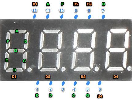
- 4-digit 7-segment display (12 pin)
- Tripod
- Camera
Project: Light-Sensitive and Adjustable Dynamic Time-Lapse Photography
By Holden Leslie-Bole
Approximate cost: $70 without the camera
I’ve been doing some time-lapse photography with my GoPro HERO3 for a while now, and I’ve gotten some great footage. There have been times, however, when I’ve wanted to be able to use my DSLR to have more control over the shots that I’m getting. I had the idea to use an infrared shutter controlled by an Arduino to be able to operate the camera remotely—I could put the circuit in a weatherproof box so that I wouldn’t have to mount it directly on the camera either.
I got to thinking that if I were using an Arduino, I could add some other cool features to my time-lapse photography rig. One problem that I’ve encountered when doing GoPro time-lapse is that when I set it up for a sunset shoot, if I don’t time it exactly right, I may end up with a few hundred dark and uninteresting pictures. I decided to add a photoresistor to act as a sensor of ambient light levels. Depending on what threshold the user programs, the camera will start taking pictures when it gets light enough in a morning shot, or stop taking pictures after the sun goes down and it gets dark. Feel free to play around with the values on this to get a light response level that suits your needs!
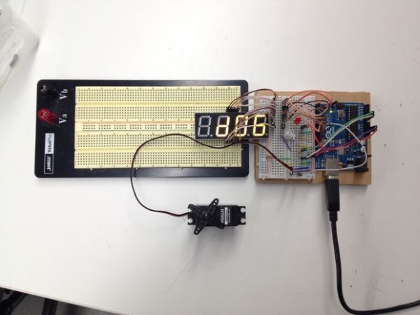
I also added a potentiometer to allow the user to control the interval between pictures on the fly without having to reprogram the Arduino. This way, you could make the time lapse to speed up or slow down over the course of a shot for dramatic effect. There is a multi-digit seven-segment display that shows whatever delay (in seconds) that the user sets.
Since many time-lapse enthusiasts are interested in adding a dynamic element to their shots, I included functionality for a servo-controlled rig that could allow the camera to rotate or pan across a scene.
This circuit is designed to be used with an infrared remote shutter. I designed this for a Nikon D3100, but any other DSLR with a remote should work just as well. In this circuit, an LED currently acts as a stand-in for the remote shutter, but adapting it for the shutter is only a matter of bypassing the button in the remote and controlling it with the Arduino. Since it is difficult to tell when an infrared transmitter is activated, the seven-segment display flashes each time a picture is taken to inform the user of its progress.
Overall, this project was designed mostly as an exercise in becoming more proficient with Arduino. For that reason, I haven’t included any instructions for mechanical dynamic rigs, but if you come up with one, please link the design in the comments! I’d love to see it.
Step 1: Parts and Materials
Breadboard (or two if you need the room)
Photoresistor
Potentiometer
Jumper wires
10kΩ resistor
Servo
Camera remote shutter
4-digit 7-segment display (12 pin)
Tripod
Camera
- How does the system determine when to start or stop taking pictures?
The photoresistor acts as a sensor of ambient light levels, triggering the camera based on user-programmed light thresholds. - Can I adjust the time interval between shots while the project is running?
Yes, a potentiometer allows the user to control the interval between pictures on the fly without reprogramming the Arduino. - What component provides visual feedback when a picture is taken?
A multi-digit seven-segment display flashes each time a picture is taken to inform the user of its progress. - Does this circuit work with any type of camera?
It is designed for DSLRs with a remote shutter, such as the Nikon D3100, but should work with any other DSLR with a remote. - How can I add movement to my time-lapse shots?
You can include functionality for a servo-controlled rig that allows the camera to rotate or pan across a scene. - What is the approximate cost of the electronics for this project?
The parts, excluding the camera, should be under $70, though adding a mechanical rig may increase the cost. - How does the circuit simulate the camera shutter during testing?
An LED currently acts as a stand-in for the remote shutter to demonstrate activation since infrared transmitters are difficult to see. - Is it possible to make the time lapse speed up or slow down dynamically?
Yes, adjusting the potentiometer allows you to change the delay to speed up or slow down the time lapse over the course of a shot.