
Summary of Webster: A Geometric Pattern Weaving Machine
This article details "Webster," a 3-axis robot developed by three architecture students to weave geometric patterns inspired by Islamic tiling and geodesic domes. The machine utilizes stepper motors, hot glue extrusion, and script-generated density to rapidly prototype dome structures through an additive web-like process. It combines structural glue textures with Z-axis movement to create complex forms.
Parts used in the Webster Project:
- 5x 3D Printer belts
- 10x Pullies
- 6x Aluminum Rods (5/32" D)
- 2x .5"D Wooden Dowels
- 2x Steel Rods (18")
- 2x 3" Long Aluminum Tubing
- 2x Acrylic Spacers (6/32" D)
- 10x Linear Bearings
- 3x Sheets of 1/4" Plywood (24" x 48")
- 6/32" Screws
- 100x Lock Nuts
- 16x Wing Nuts
- 100x Washers (Nylon and Metal)
- Set of Small Rubber Clamps
- 1x Low Temp Mini Glue Gun
- Tons of hot glue
- 4x Gears
- 1' x 1' Sheet of 1/8" Acrylic or Wood
- Multiple Packs of Mini Glue Sticks (.27 Diameter)
- 3x Stepper Motors (one single headed, two dual headed)
- 1x Continuous Loop Servo Motor
- 1x Quad Shield Motor Driver
- 1x Small Computer Fan
- 3x Heat Sinks
- Female Headers
- 2x 12 Volt Power Adapters
- Stranded Wire
- Soldering Iron and Solder
- 2x Arduino Uno's
- 1x Blank Shield
- Tons of zip ties
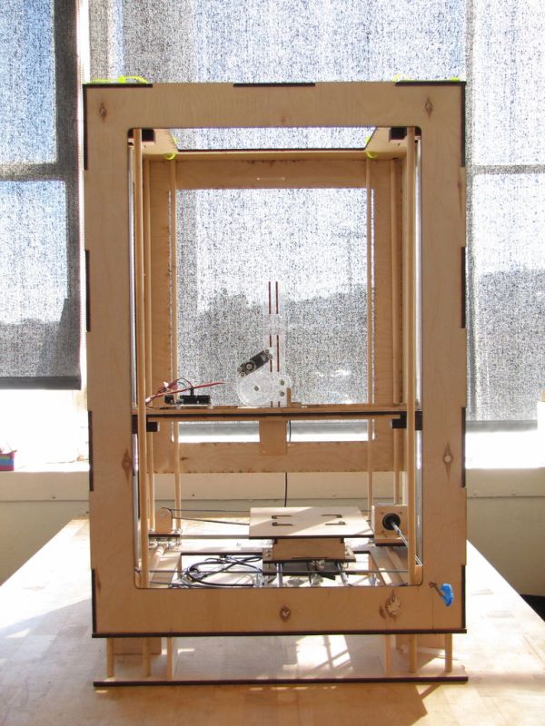
We are three students from California College of the Arts in San Francisco in the Architecture program. This studio is called Creative Architecture Machines and is taught by Jason Johnson and Michael Shiloh. Webster is a geometric pattern weaving machine that takes inspiration from Islamic tiling, geodesic dome construction, weaving machines, and conventional 3D printers. This 3-axis robot was an exploration in the geometric control of stepper motors, the texture variability of hot glue extrusion, and weaving facets through script-generated density difference and form repetition. Harnessing the structural capacity of the glue texture, the movement of the z-axis motor, and the variability of the weave, Webster was used to rapid-prototyping domes through an additive web-like process.
 Please see the attached video for more visual information on the process and final product. If you are interested in more information about the process or have any questions regarding the setup please feel free to contact us. We would love to hear feedback or suggestions as well.
Cassondra Stevens, Colette Rixey, and Megan Freeman
Step 1: What You’ll Need
INGREDIENTS
For the Body…
(5) 3D Printer belts. You can order one length of belt and cut it down to 5 separate pieces.
(10) Pullies. Make sure they fit to the printer belts.
(6) Aluminum Rods (5/32″ D). The height of the rod depends on the height of your desired Z axis.
(2) .5″D Wooden Dowels. Same length as base.
(2) Steel Rods. The Diameter needs to match the motor head diameter. Length of the rod depends on the width of the base. Ours were 18″.
(2) 3″ Long Aluminum Tubing. This is need to snuggly fit over the steel rod and the motor head (it attaches the two together).
(2) Acrylic Spacers. Diameter needs to fit over the standard chosen screw size. We used 6/32″ D.
(10) Linear Bearings. These need to perfectly slide over the 5/32″ D Aluminum Rods.
(3) Sheets of 1/4″ Plywood (24″ x 48″)
6/32″ Screws. We bought 3 boxes of 100 screws at various lengths .75″ 1″, 1.25″
(100) Lock Nuts
(16) Wing Nuts. To allow you to adjust the belt.
(100) Washers, Nylon and Metal
Set of Small Rubber Clamps to be your extra hands.
For the Extruder…
(1) Low Temp Mini Glue Gun. You should buy multiple backups. We went through 10.
Tooons of hot glue
(4) Gears. Various sizes.
1′ x 1′ Sheet of 1/8″ Acrylic or Wood
Screws 6/32″ D. You can use the screws that are listed for the body.
Multiple Packs of Mini Glue Sticks .27 Diameter
Electronics…
(3) Stepper Motors, one is single headed and two are dual headed
(1) Continuous Loop Servo Motor
(1) Quad Shield Motor Driver
(1) Small Computer Fan
(3) Heat Sinks
Female Headers. To solder to motor driver
(2) 12 Volt Power Adapter
Stranded Wire
Soldering Iron and Solder
(2) Arduino Uno’s
(1) Blank Shield
Tons of zip ties
Step 2: Building The Base (X and Y)
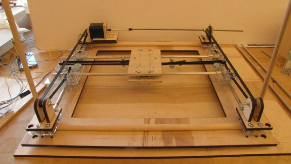
Start at the bottom and build up.
Cut out a 19″ x 23″ piece of 1/4″ Plywood. This is a base for the machine to rest on.
Cut out the structure for the X and Y bed, a 19″ x 19″ x 1/4″ D Plywood Square with 13″ x 13″ hole cut out of the center.
You’ll need to cut out 4 sets of holes at each corner. Please refer to laser file attached.
Cut out remainder of pieces on laser file. Please refer to image for assembly.
Screw “A” pieces into the corners to secure wooden dowels.
Place Aluminum rods down perpendicular to wooden dowels.
Make sure you slide 2 linear bearings on to each aluminum rod before securing it down.
Sandwich aluminum rods between “A” and “B” pieces. Do this in each corner.
Add the vertical “C” pieces in 3 corners. The fourth corner will have two vertical “D” pieces that sandwich the X motor in place.
Run a screw with a Nylon spacer over it through each pair of “C” tabs.
Place the remaining two aluminum rods perpendicular to the ones directly below them. Make sure to slide one linear bearing onto each of these before securing down. Please refer to image to see how the aluminum rods attach to each other.
Now you attach the bed. The linear bearings need to be directly across from one another and the held in place by the bed.
For more detail: Webster: A Geometric Pattern Weaving Machine
- What is the primary function of the Webster machine?
It is a 3-axis robot designed for rapid-prototyping domes through an additive web-like process using geometric pattern weaving. - How many 3D printer belts are required for the body?
You need five 3D printer belts, which can be ordered as one length and cut down into five separate pieces. - Can I use any size screws for the assembly?
The project specifically uses 6/32" screws, and it recommends buying three boxes containing various lengths like .75", 1", and 1.25". - What type of motor driver is used in the electronics section?
The build requires one Quad Shield Motor Driver connected to female headers via soldering. - How do you adjust the belt tension on this machine?
Wing nuts are used to allow you to adjust the belt tension during assembly. - What material is used for the base of the machine?
The base is constructed from a 19" x 23" piece of 1/4" Plywood. - Does the machine require multiple glue guns?
Yes, the authors recommend buying multiple backups because they went through ten low temp mini glue guns during the project. - How are the linear bearings secured in the X and Y bed structure?
Linear bearings slide over the aluminum rods before the rods are sandwiched between wooden pieces and secured with screws. - What is the diameter of the steel rods used for the motor head attachment?
The steel rod diameter needs to match the motor head diameter, though the specific length depended on the width of the base. - How many Arduino boards are needed for the electronics setup?
The project requires two Arduino Uno boards along with one blank shield.