According to Ancient Greek mythology, Artemis and Apollo were immortal twins born ages ago on a rocky island in the Aegean Sea. Artemis, her hunting bow poised and fleet feet padding the forest floor, reigned as Goddess of the Moon. Her twin brother, Apollo, strummed his harp and recited poetry from his throne as God of the Sun. Using an Arduino UNO microcontroller and a simple photo resistor (sensor), you can recreate this mythological pair as elegant figurines that dance according to their divine preference. Apollo, ever dazzling, dances in the light of day, while Artemis, forever fierce, dances in the shadow of night.
A half-opaque, half-transparent acrylic rotates at the top to the model, creating a varying input of light for the photo resistor light sensor housed on the back of the eagle. When the transparent acrylic half is above the sensor, the light is detected and the Arduino activates the motor for the Apollo figurine. When the opaque acrylic half is above the sensor, no light is detected and the Arduino activates the motor for the Artemis figurine.
This project utilizes simple gear and cam machinery paired with stepper motors to move two wooden figurines. The actions of the motors are controlled by an Arduino UNO that uses a photo sensor to detect varying light input.
This project began as an assignment to integrate Arduino technology with the tradition of moving automata in the Things That Think course by Ann and Mike Eisenberg at the University of Colorado Boulder. According to Ancient Greek mythology, Artemis and Apollo were immortal twins born ages ago on a rocky island in the Aegean Sea. Artemis, her hunting bow poised and fleet feet padding the forest floor, reigned as Goddess of the Moon. Her twin brother, Apollo, strummed his harp and recited poetry from his throne as God of the Sun. Using an Arduino UNO microcontroller and a simple photo resistor (sensor), you can recreate this mythological pair as elegant figurines that dance according to their divine preference. Apollo, ever dazzling, dances in the light of day, while Artemis, forever fierce, dances in the shadow of night.
A half-opaque, half-transparent acrylic rotates at the top to the model, creating a varying input of light for the photo resistor light sensor housed on the back of the eagle. When the transparent acrylic half is above the sensor, the light is detected and the Arduino activates the motor for the Apollo figurine. When the opaque acrylic half is above the sensor, no light is detected and the Arduino activates the motor for the Artemis figurine.
This project utilizes simple gear and cam machinery paired with stepper motors to move two wooden figurines. The actions of the motors are controlled by an Arduino UNO that uses a photo sensor to detect varying light input.
This project began as an assignment to integrate Arduino technology with the tradition of moving automata in the Things That Think course by Ann and Mike Eisenberg at the University of Colorado Boulder.
Step 1: Setting up the Motor Shield

Materials:
1 * Adafruit Motor/Stepper/Servo Shield for Arduino kit – v1.0
Tools:
soldering iron
solder
wire clippers
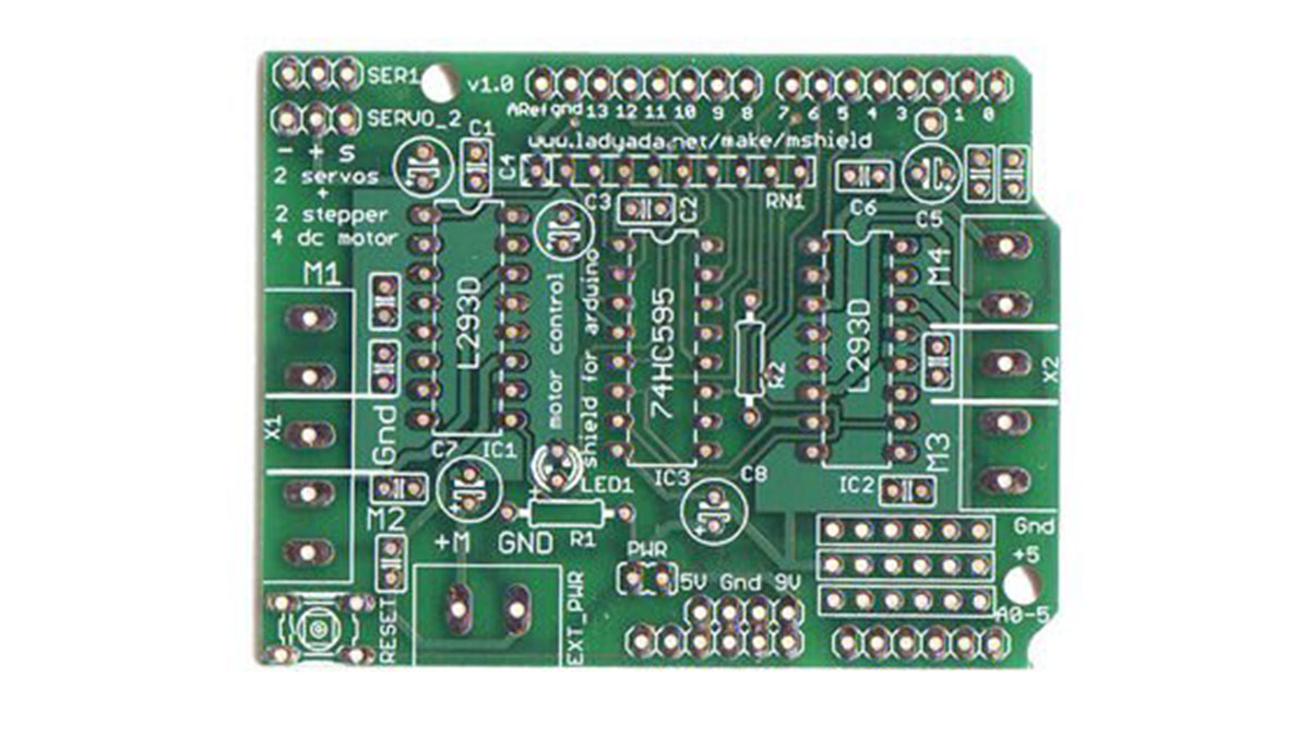
In order to connect our three motors to the Arduino Uno, we opted to use a motor shield. A motor shield fits on top of the Arduino and, once set up, allows the easy connection of up to three motors, including all resistors and chips necessary. The motor shield we used for this particular project was the Adafruit Motor/Stepper/Servo Shield Kit v1.0 available at http://www.adafruit.com/products/81.
When the motor shield arrived it was unassembled, so we put it together following Adafruit’s online soldering tutorial. (http://www.ladyada.net/make/mshield/make.html) The tutorial is very straightforward to follow, although some parts look different from those in the example pictures, so make sure to take note of that if you use this particular motor shield kit. If it is your first time soldering, be sure to practice with the soldering iron and solder a few times before you begin setting up the motor shield. This kit is completely feasible for a first time solderer (as we had in our group) but it will require some patience.
Step 2: Choosing your motors
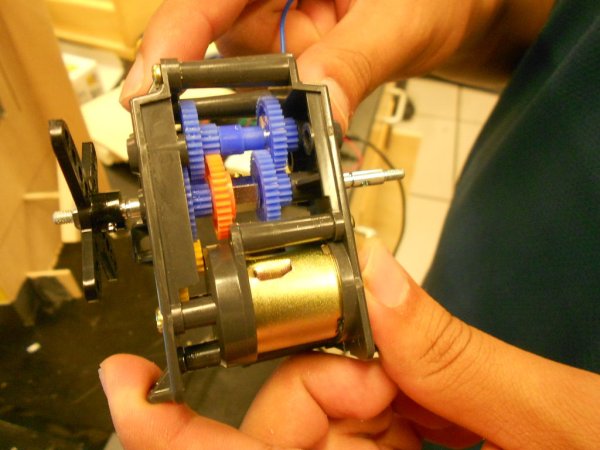
The motors required for rotating each of the automaton need gear boxes because the torque required to turn each of the automaton is greater than the amount of torque each dc motor by itself gives. One needs to understand the amount of voltage required for each dc motor before buying one because the arduino cannot supply enough power as the amount of motors you have increases.
2 * dc motors
1 * servo motor
2 * gearboxes
Tools:
tools required to build each gear box is usually supplied by the gear box kit
Steps:
1.) Choose the gear ratios for each gear box based on how much torque you need.
2.) Higher gear ratios give more torque.
3.) Choose a servo motor which can go 360 degrees because majority of servo motors cannot and only go from 0-180.
Step 3: Make the circuit logic
The logic is for the connection between the photo resistor and the arduino board.
arduino photo resistor
1 * 1k ohm resistor
3 * small wires
1 * perforated board
Tools:
solder
soldering iron
blue= 3 wires
purple=perforated board cut into smaller pieces
green= 1k ohm resistor
red=header pins to fit into the top of the motor shield
You need to create a circuit similar to the 2nd picture.
where the arduino is pin 0 analog input on the motor shield
1.) Cut perforated board so you have enough space to put logic in it
2.) Solder the header pins into the board so it is able to be placed directly on top of the board
3.) Solder 1k ohm resistor into perforated board.
4.) Solder wire from 5 v header pin to 1k ohm resistor.
5.) Solder wire from header pin arduino input socket 0 to other side of 1k ohm resistor.
6.) Solder wire from ground header pin to a spacious place near where you soldered from the previous step
The next step will be assembling the photo resistor.
For more detail: Artemis & Apollo: Dancing with Arduino and light detection


