
Summary of Create KiCAD schematics automatically with Schematic-o-matic
This project, Schematic-o-matic, automates KiCAD schematic generation from physical breadboards. It uses a custom instrumented breadboard connected to an Arduino Due to map electrical continuity via Python. Users place components on the board (removing ICs during testing to avoid false positives), and the script identifies connections and pin locations using KiCad library files to generate a complete schematic in EESchema format.
Parts used in the Schematic-o-matic:
- Instrumented breadboard with soldered wires
- Arduino Due board
- Python script
- PC running the Python script
- KiCad library files
- EESchema Schematic File Version 4
Electronics hobbyists, engineers and developers looking for an automatic way to create KiCAD schematics may be interested in your project created by Nick Bild, capable of analyzing your physical breadboard and automatically generating a KiCAD schematic. Although it is worth mentioning that the script is have some limitations such as many ICs either don’t have internal continuity for every pin or only have internal continuity in certain states. Watch the demonstration video below to learn more about the project and how it can help you automatically generate KiCAD schematics directly from your breadboard project or prototype.
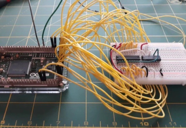
Schematic-o-matic automatically creates KiCAD schematics
“A breadboard is, at its core, a series of connectors. This script’s purpose is to identify every connection and associate it with the corresponding pin on a component. It is able to do that using a special breadboard that has every row of pins connected to an Arduino Due board I/O pin. A Python script running on a connected PC then checks every row for continuity. The user then inputs the component located at connection, and the script will draw a KiCAD schematic with wires between every component’s pins.”
The first step in the process is to use a specially instrumented breadboard to build your circuit on. Each continuous conductive region on the breadboard has a wire soldered to it on the underside of the breadboard. This allows for a methodical test for electrical continuity between each region, which was accomplished by using an Arduino Due. Because certain components (e.g. ICs) can cause false positives for connections between regions due to internal conductances, they must be removed from the board before running the Arduino code. The output of the code is a map of the electrical connections between regions (i.e. wire placements).”
“To determine the location of all component pins (with respect to the specified pin 1) on the breadboard, the script parses the associated KiCad library file. The components are added to a KiCad schematic (EESchema Schematic File Version 4 format), after which the wires are then added, according to the connections information collected through continuity testing, with the help again of KiCad library files to determine the locations of all pins to place wires in the correct locations. The plain text, open formats used by KiCad made this integration possible.”
Source: Create KiCAD schematics automatically with Schematic-o-matic
- How does the system identify connections?
The system uses an Arduino Due to check every row for electrical continuity. - Can I leave ICs on the breadboard during testing?
No, ICs must be removed before running the code because internal conductances can cause false positives. - What format does the generated schematic use?
The output is created as an EESchema Schematic File Version 4 file. - How does the script know where to place component pins?
The script parses KiCad library files to determine the location of all component pins relative to pin 1. - What hardware connects the breadboard regions to the computer?
Wires soldered to the underside of the breadboard connect each continuous conductive region to an Arduino Due I/O pin. - Does the tool work with any breadboard?
No, it requires a specially instrumented breadboard where every row of pins is connected to an Arduino Due board I/O pin. - Why are plain text open formats important for this project?
The plain text open formats used by KiCad made the integration between the continuity map and the schematic possible. - What happens after the script collects connection information?
The script draws a KiCAD schematic with wires between every component's pins based on the collected data.
