
Summary of SIMPLE FIXTURE DETERMINES LEAKAGE OF CAPACITORS AND SEMICONDUCTOR SWITCHES
The article describes a simple fixture that uses an AD8661 voltage-follower op amp and an ADR391 2.5 V reference to measure very small leakage currents of capacitors and semiconductor switching devices. A capacitor under test (CUT) is charged to 2.5 V, then isolated; after a measured interval the follower output is read with a DVM. Leakage current is computed as C × ΔV_O / t_MEAS. The fixture can also test reverse-biased diodes and off-state transistors by substituting the DUT in parallel with an added capacitor.
Parts used in the Simple Fixture Determines Leakage of Capacitors and Semiconductor Switches:
- Analog Devices AD8661 op amp (voltage follower)
- Analog Devices ADR391 precision 2.5 V reference
- Capacitor under test (CUT)
- Added capacitor (CADD) for DUT testing
- Device under test (DUT): reverse-polarized diodes, JFETs, MOSFETs, BJTs, SCRs, IGBTs
- Digital voltmeter (DVM)
- Switch or mechanism to connect/disconnect Point A to the reference
The circuit in Figure 1a comprises a voltage follower, IC1 , and the reference-voltage source of IC2. IC1 is an Analog Devices AD8661 op amp, which has a guaranteed input-bias current of no more than 1 pA and a typical input-bias current of 0.3 pA (Reference 1), and IC2 is an Analog Devices ADR391 precision voltage reference (Reference 2).
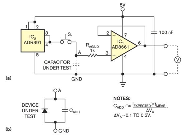
The manufacturer trims the input offset voltage of this op amp not to exceed 100 µV, and the typical value is 30 µV. These properties suit this amplifier for observing self-discharging of almost any type of capacitor. The leakage currents of solid-tantalum capacitors and those having high-quality plastic dielectrics are well above the input-bias current of voltage follower IC1. The CUT (capacitor under test) initially charges to the reference-voltage level of 2.5V by connecting Point A to the output of IC2. Subsequently, at some convenient time, Point A disconnects from the source of the reference voltage. A DVM (digital voltmeter) measures the output voltage of the follower at some reasonable time.
The measured voltage drop, VO, with regard to initial value, should be 0.1 to 0.5V. The leakage current, IO , is C×ΔVO /tMEAS , where C is the value of the CUT and tMEAS is the time between releasing the connection of the CUT to the 2.5V source and the instant of readout at the voltage drop of VO.
The fixture also allows determining leakage currents of reverse-polarized diodes and of various switching devices in the off state, such as JFETs, MOSFETs, BJTs (bipolar-junction transistors), SCRs (silicon-controlled rectifiers), and IGBTs (insulated-gate bipolar transistors). In this case, the parallel combination of the DUT (device under test) and the added capacitor, CADD , replaces the CUT (Figure 1b).
Read more: SIMPLE FIXTURE DETERMINES LEAKAGE OF CAPACITORS AND SEMICONDUCTOR SWITCHES
- How is the capacitor under test initially charged?
The CUT is charged to the 2.5 V reference by connecting Point A to the output of IC2. - How is leakage current calculated for the CUT?
Leakage current IO is calculated as C times ΔVO divided by tMEAS: IO = C × ΔVO / tMEAS. - What op amp is used as the voltage follower and why?
The AD8661 is used because it has very low input-bias current (guaranteed ≤1 pA, typical 0.3 pA) and a low trimmed input offset (≤100 µV), suitable for observing capacitor self-discharge. - What reference source is used to set the initial voltage?
The ADR391 precision voltage reference provides the 2.5 V initial charging level. - What voltage drop should be measured for accurate results?
The measured voltage drop ΔVO relative to the initial value should be about 0.1 to 0.5 V. - What measurement instrument is used to read the follower output?
A digital voltmeter (DVM) measures the follower output voltage. - Can the fixture test semiconductor switches as well as capacitors?
Yes; for semiconductor testing the parallel combination of the DUT and added capacitor CADD replaces the CUT. - What types of semiconductor devices can be tested in this fixture?
Reverse-polarized diodes, JFETs, MOSFETs, BJTs, SCRs, and IGBTs can be tested in the fixture.
