Summary of Deej – a Physical Volume Mixer
deej is a DIY physical volume mixer that allows users to adjust application audio levels in real-time without closing games or apps. The project utilizes an Arduino Nano, slide potentiometers, custom PCBs, and 3D-printed housing components. It combines hardware assembly with open-source software to create a desktop tool for managing Discord, Spotify, and game volumes efficiently.
Parts used in the deej Physical Volume Mixer:
- Slide Potentiometers
- Knobs
- Arduino Nano
- Male header pins 2.54mm
- M3 x 5mm Round Head screws
- M2 x 4mm Countersunk screws
- Custom PCB
- White PLA filament
- Blitz Sapphire filament
- 6 pin 2.54 mm male header
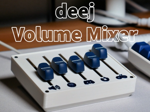
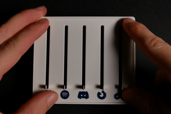
Meet deej!
deej is a physical voulume mixer. Just like the volume mixer built into windows, just physical! This means that you can change the volume of an application without closing your important game. You can turn the game volume down and Discord volume up, when someone joins the call, and turn the Spotify volume up when your beat comes on. Since it sits right beside your keyboard you can quickly change volume, for example if a game has a loud intro music (looking at you Civ 6).
Let’s get started!
Step 1: Watch the Video!
I made a video showing the build process, give it a watch!
Step 2: Ordering Parts
You can get the full kit from my site, Ananords.com!
Get just the PCB here (or preorder V2 of the PCB)
The parts I used are linked below:
Slide Potentiometers: (AliExpress or Amazon)
Knobs: (AliExpress or Amazon)
Arduino Nano: (AliExpress or Amazon)
Male header pins 2.54mm : (AliExpress or Amazon)
M3 x 5mm Round Head (AliExpress or Amazon)
M2 x 4mm Countersunk (AliExpress or Amazon)
Custom PCB (see next step or order above)
Step 3: PCB – Schematic
I used EASYEDA to design the PCB’s.
You can get the EASYEDA file to the PCB here (please note that the markings on the pcb might be wrong, working on fixing it)
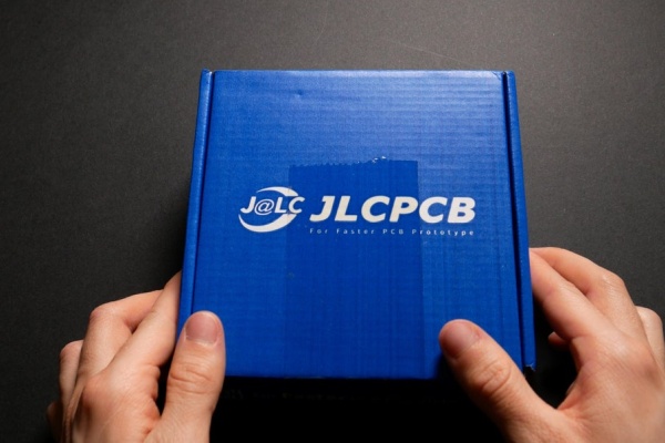
I ordered my PCB’s from JLCPCB. You can get 5 pcs for only 2$!
You can also get the PCB’s from my website:)
Get just the PCB here (or preorder V2 of the PCB)
You can also try to make one with protoboards. You might have to change the CAD model a bit though…
Step 4: Start Printing!
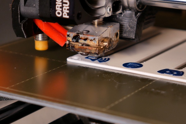
The “first” step is to print the base and plate.
I printed the base and top plate in white PLA, and for the blue logos I used Blitz Sapphire by AddNorth.
Both are printed with .15 layer height, and 20% infill.
Link to the 3D files:
STL:
FUSION 360:
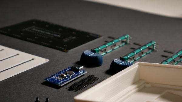
Step 5: Solder the Arduino Board
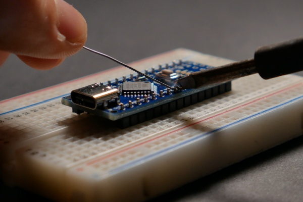
While printing, you can start assembling and soldering the electronics!
You first need to solder pins to the Arduino, if yours doesn’t already have them.
Then, you can break off the middle piece of the PCB (the Arduino daughter board). To do this, simply press in the middle PCB until the mouse bites breaks, and the PCB becomes loose.
Now you can solder the Arduino to that board.
The Arduino PCB also needs some pins to connect to the potentiometer board. You can use some wires, or a 6 pin 2.54 mm male header.
Do not solder the Arduino PCB to the Potentiometer board, or the potentiometers yet!
Step 6: Assembling the PCB’s
If the 3D prints are not done yet, you can do step 8 and 10 before this:)
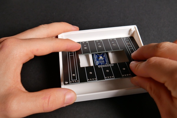
You first need to insert the Arduino board into the base.
Then, carefully insert the potentiometer PCB into the base, and carefully line up the pins from the Arduino PCB with the holes on the potentiometer PCB. Make sure it is fully mounted.
Now, solder the pins to connect both boards together. When you have done that, you can slowly remove both cards from the base.
Step 7: Solder the Potentiometers
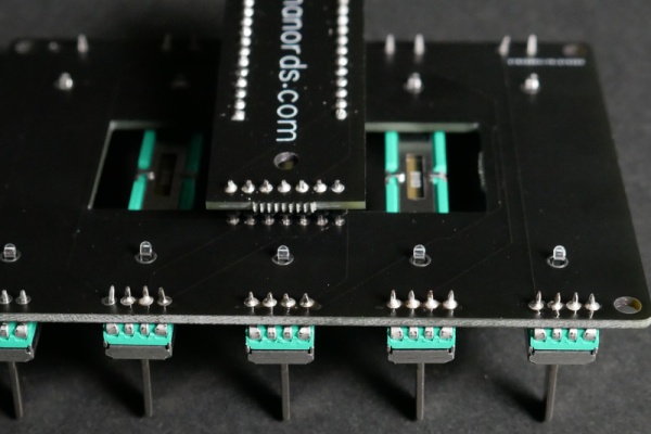
Insert all the potentiometers into the PCB, and solder them.
Make sure that all the potentiometer pins are going through the correct holes, and that they are fully inserted before soldering!
You can now insert the two PCB’s back into the base.
I found that using a screwdriver to push the Arduino PCB in place helped a bit.
Use the four M3 screws to secure the PCB.
Step 8: Upload the Code
Start by making sure you have Arduino IDE installed. (If not, you can download it here)
Then, go to the official deej GitHub page and download the latest Arduino code:
Then, choose Arduino Nano as your board, and upload the code to the Arduino. (for more details)
PS: I had problems with my Arduino Nano, try to use “328p Old Bootloader” if you have problems uploading too.
You can now open the Serial Monitor, and you should be able to read the values from all the potentiometers! The value should be between 0 and 1023.
Thanks to Omri Harel for making this Open Source!
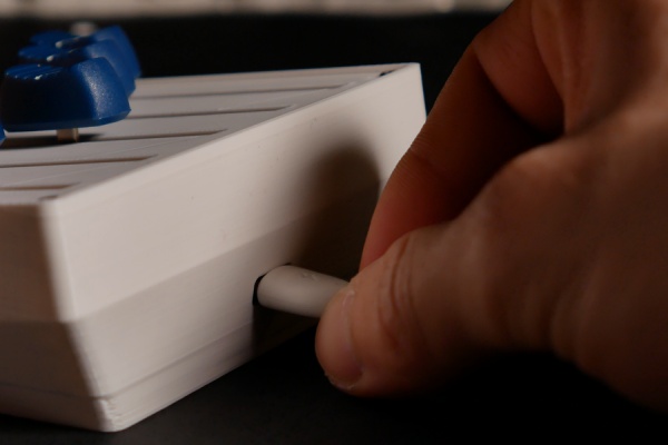
Step 9: Final Assembly
Now that you know everything works, you can assemble it together!
Take the top plate, and place it on top.
Then, take your four M2 screws and screw them in to mount the top plate.
The knobs should be easy to install, by just pressing them onto the sliders.
I also recommend gluing some rubber feet underneath to stop it from sliding.
Step 10: Software
LINUX:
Install libgtk-3-dev, libappindicator3-dev and libwebkit2gtk-4.0-dev for system tray support
Pre-built Linux binaries aren’t currently released, so you’ll need to build from source.
WINDOWS:
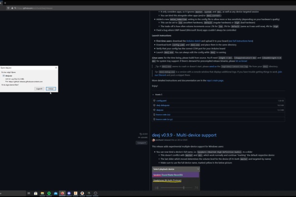
First, head over to the releases page on the GitHub site to download the latest version of the executable and configuration file. (deej.exe and config.yaml)
After downloading, place both files in the same folder in a directory anywhere on your machine (For example, Documents)
To make it run on boot, create a shortcut of deej.exe, and copy it to ” %APPDATA%\Microsoft\Windows\Start Menu\Programs\Startup “
Configuration
Now that you have downloaded the software, you have to edit the config file to choose what programs to control, and to set the correct COM port, so it can connect to the Arduino.
To do this, you can right-click the config.yaml file, click “open with” and choose notepad (or better, notepad++ if you have that)
You can also just launch the program and right-click the icon in the system tray, then choose edit configuration.
Here you can set up your programs, and choose COM port. The COM port should be the same as the one you programmed your Arduino with.
For more information on what you can change in configuration, check out the GitHub!
Step 11: Done!
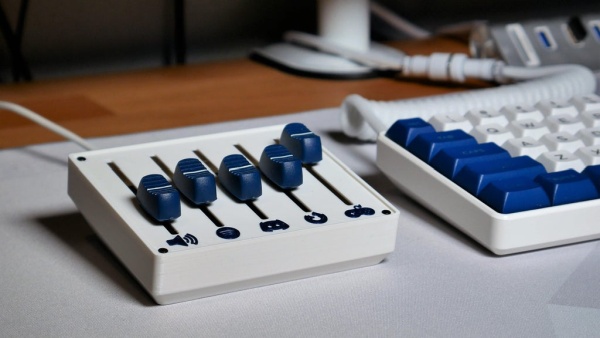
You have now created your own physical volume slider!
Hope you like the tutorial:)
Any questions? Just ask, and I will try to answer them!
Follow me on Instagram for updates on upcoming projects:)
Instagram: https://www.instagram.com/ananordss/
Contact me: [email protected]
••• Support me •••
Patreon: https://www.patreon.com/ananords
Donations: https://ananords.com/products/donation/
Buy me a coffee: https://ananords.com/products/donation/
Source: Deej – a Physical Volume Mixer
- What is the primary function of the deej device?
It is a physical volume mixer that lets you change the volume of specific applications like games or Discord without closing them. - How can I order the parts for this project?
You can get the full kit from Ananords.com, purchase just the PCB, or buy individual components like potentiometers and knobs from AliExpress or Amazon. - Which software tools were used to design the PCB?
The author used EASYEDA to design the PCBs and ordered the boards from JLCPCB. - What are the recommended printing settings for the case?
The base and top plate should be printed with .15 layer height and 20% infill using white PLA and Blitz Sapphire for logos. - How do I connect the Arduino board to the potentiometer PCB?
You can use wires or a 6 pin 2.54 mm male header to connect the two boards before soldering them together. - What should I do if I have trouble uploading code to my Arduino Nano?
If you face upload issues, try selecting the "328p Old Bootloader" option in the Arduino IDE. - How do I configure the software to control specific programs?
Edit the config.yaml file using Notepad or Notepad++ to select programs and set the correct COM port matching your Arduino. - Can I make the software run automatically when Windows starts?
Yes, by creating a shortcut of deej.exe and copying it to the Startup folder located at %APPDATA%MicrosoftWindowsStart MenuProgramsStartup.