
Summary of Arduino controlled Interactive wallpiece
This article details a DIY interactive wall piece controlled by an Arduino UNO, featuring touch-activated light displays. The project utilizes capacitive sensing on metallic surfaces to trigger LEDs without external hardware. Two specific designs are described: a "Robo" with glowing eyes and shield lettering, and a flower piece. The system relies on connecting thin metal wires from sensing areas to digital pins 8–12 and controlling output LEDs via pins 3–7.
Parts used in the Interactive Wallpiece:
- Arduino UNO board
- Metallic wire for touch sensors
- Thin metallic sheets (silver color)
- Blue LEDs
- Ground connections
- Positive supply wires
This project is a subset of my idea of an interactive wall.. so this is an interactive wall-piece..
What does it do ? Mine is a touch activated light display.
How does it work? It is controlled by an Arduino UNO which senses the inputs and turns on the respective outputs.
Step 1: Building the touch sensor
If u have an Arduino board, building a touch sensor is a cakewalk..
U dont need ny external hardware to get the sensing functionality.
All u need to do is upload the following code on ur board, turn on ur serial monitor and then touch the metallic wire to see the change in the value. 🙂
What does the code do? It returns the time that the pin takes to discharge. When it is touched, it takes more time to discharge. U need to adjust the threshold to currectly identify a touch.
Even If u cant understand the function which calculates the value of the pin, it is perfectly ok.. There are only 2 modifications needed according to ur design.
1) The number of touch sensing u want
2) Threshold setting
Here’s a lil shaky video about how u can see the difference in the capacitance value of a pin when u touch it. <my camera wasn able to focus well so>
Lemme explain what happens in the video. When the pin is not touched, I get the value 1 at the pin [as can b seen on the serial monitor]. When the pin is touched, the value goes higher than one, depending on how much u press the wire. Again when released, the pin value goes back to one.
Once the sensing goes well, we build the whole contraption!
 capacitive_touch.ino
Step 2: Build the design
We shall first see the simpler one, which is the steel colored Robo.
Function : Touch anywhere on the face and the eyes glow.
Touch anywhere on its shield and see the ‘A’ glow.
For building the Robo, I used thin metallic sheets of silver color.
The connections are simple. Just connect a thin metal wire from the sensor areas [2 in this case: face and shield] to any of Arduino digital pins 8 to 12. [They say even 13 works but my trials found it wasnt as reliable as other pins]
Connect the 2 blue LEDs together [for the eyes] and connect the ground to the common Arduino Ground and the Positive supply wire to other Arduino digital pins [3 through 7 were the pins where I connected the outputs and 8 through 12 were the input pins]
Sorry got no pics of the robo while it was built..
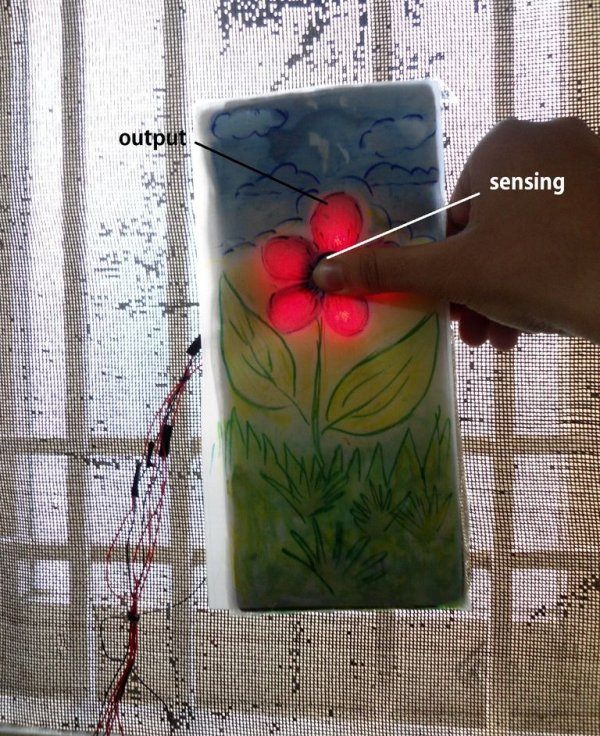
Now we go through the building of the flower piece contraption. Its a lil tricky!
For more detail: Arduino controlled Interactive wallpiece
- How does the touch sensor work?
The code returns the time a pin takes to discharge; touching the wire increases this discharge time. - What external hardware is needed for sensing?
No external hardware is required as the Arduino senses inputs directly through the metallic wire. - Which Arduino pins should be used for input?
Digital pins 8 through 12 are recommended for input sensing, as pin 13 was found unreliable. - Which Arduino pins control the output LEDs?
Pins 3 through 7 were used to connect the positive supply wires for the LED outputs. - What happens to the serial monitor value when touched?
The value changes from 1 to higher than one depending on how much pressure is applied to the wire. - What modifications are needed for the code?
You only need to adjust the number of touch sensors and the threshold setting based on your design. - Can I use any digital pin for the output LEDs?
The author connected outputs to pins 3 through 7, but the text implies flexibility within the available digital pins. - What material is used for the Robo face and shield?
Thin metallic sheets of silver color are used to build the Robo structure.
