Summary of Mint Tin Hero using Arduino
The author transformed a Trader Joe's green tea mint tin into a portable Guitar Hero-style rhythm game. The project utilizes the tin's metal body and clear plastic lid as a drum interface, controlled by a single sensor. An Arduino microcontroller processes inputs to drive an LCD screen and speaker for gameplay and cheesy music. Due to space constraints, the circuit required compact soldering on a small PCB, using two 3V batteries to power the system directly without a voltage regulator.
Parts used in the Mint Tin Hero:
- Trader Joe's green tea mint tin
- Arduino microcontroller
- LCD screen (8x2 or 16x2)
- Small speaker
- Single sensor
- Battery holder
- Two 3V batteries
- Soldering iron and solder
- Headers (cut into 3x2 and 4x1 configurations)
- Circuit board (PCB)
A friend at work proposed a friendly competition between a few co-workers: to make something cool out of a Trader Joe’s green tea mint tin. Anything – whatever our creative hearts desired. The prize? Nobody cared – we’d figure that part out later.
I thought it would be fun to do something electronic with it – maybe even squeeze an Arduino in there. But it would be tough – the tin was pretty tiny. And it had a clear plastic screen on the cover. I had to figure out what to do with that…
After a night of brainstorming, and then another week or so of indecision, I settled on making a Guitar-Hero-like rhythm game, involving a single sensor, an LCD screen, and a small speaker for playing some cheesy music. I play drums, and I was kind of thinking of the whole mint tin as a drum, with the plastic screen acting like a drum head. The other side, made of metal, would host the LCD screen and speaker, facing the “player”.
(Product endorsement: Don’t worry about eating through all the mints before you start this project – they’re actually quite good…)
Files:
The schematic, Fritzing layout, and Arduino code can be downloaded here.
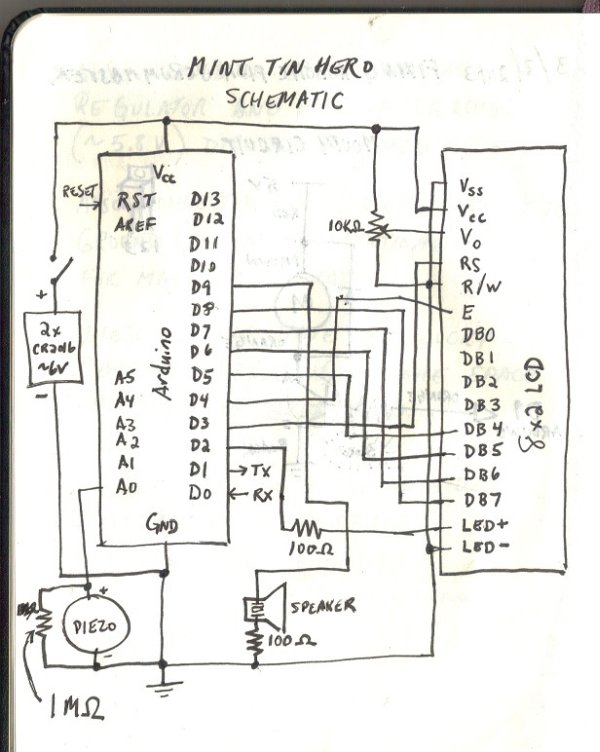
Schematic:
Step #1: Solder some of the main components on the circuit
- It’s tough to cram all this stuff on a tiny PC board. This project might test your soldering skills and/or patience. But, as with many things, if you’re getting frustrated, it’s always best to walk away and come back later. (I definitely had to do this a few times…)
- Anyway, if you take a look at the layout of the board, you’ll see that there are a lot of overlapping wires and such. The red lines are the positive (~5V) wires, the black lines are the negative (0V) wires, the gray lines are the solder lines running on the underside of the board (where the little metallic circles are), and the other colors are just other signals.
- (Note that some of the components in the diagram don’t perfectly represent the “real-world” parts – e.g. the LCD screen shown is a 16×2, rather than a 8×2, but bear with me…)
- The easiest way to start off is to get some of the big components on there: the Arduino, the battery holder, and the switch. Just dab some solder at the corners of the Arduino to hold it in place. Make sure it’s oriented the way shown in the diagram.
- The power supply for this circuit is a bit of a hack. Usually, you don’t want to run power directly from the batteries – normally, you’d want to have a 5V voltage regulator. Instead, we’re hooking up an unregulated 6V supply (two 3V batteries) right to the digital circuit. Blasphemy! It turns out that the batteries actually don’t supply enough juice to support a voltage regulator, and the Arduino and LCD module can handle the 6V ok (actually more like 5.8V). So, there you have it. Sorry if I’ve offended anyone.
Step #2: Cut up and attach the headers.
- You will need to cut up some of the headers for use on the board. You can cut them with wire snips – I would recommend just cutting directly through one of the holes, effectively “wasting” a hole between pieces. You need 2 3-hole headers placed next to each other to make a 3×2 header. This will be used for loading your code onto the Arduino later on.
- The other 4×1 header, in the upper left of the diagram, is not necessary if you are using an Arduino chip with the bootloader pre-loaded on it (e.g. a chip pulled off of an existing Arduino board). I was using a chip that did not already have the bootloader configured on it, so I needed this header to program it.
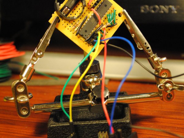
- This part is a little tricky: to connect one component to another, you need to “drag” the solder around from hole to hole on the underside of the board. This can be a little frustrating, and a “helping hands” tool definitely comes in handy here. Try connecting the leftmost pins of the 3×2 header to the Arduino pins directly next to it. I found that a good way to do this was to get a good amount of solder on both the Arduino pin and the adjacent header pin, and then put the soldering iron tip right between the two holes, and then lift straight up in order to leave a connecting line of solder between them.
LCD
Battery Holder
For more detail: Mint Tin Hero using Arduino
- What is the main function of the mint tin in this project?
The mint tin serves as the housing for the electronics, with the metal side holding the screen and speaker, and the plastic lid acting as a drum head. - Can I use a standard 5V voltage regulator for this circuit?
No, the author notes that the batteries do not supply enough juice to support a voltage regulator, so they powered the circuit directly from the unregulated 6V supply. - How are the headers prepared for the circuit board?
Headers are cut with wire snips, often wasting one hole between pieces, to create specific sizes like a 3x2 header for loading code. - What type of batteries power the device?
The device uses two 3V batteries connected to provide an unregulated 6V supply, which functions similarly to 5.8V for the components. - Is a bootloader necessary if using an Arduino chip?
A 4x1 header is only needed if the chip does not have a pre-loaded bootloader; otherwise, it is not necessary. - What tools are recommended for connecting pins on the underside of the board?
A helping hands tool is recommended to hold components steady while dragging solder between holes on the underside of the board. - Does the schematic perfectly represent the real-world parts used?
No, some components in the diagram, such as the LCD screen size, may differ slightly from the actual parts used. - What happens if you get frustrated during the soldering process?
The author suggests walking away and coming back later, as the tight layout can test patience and soldering skills.