Summary of Digital voltmeter using Arduino UNO Range:0-50 volt Using SIMULINO UNO
This project builds a simple Arduino UNO digital voltmeter (0–50 V DC) using a 10-bit ADC and a voltage divider, displaying readings on a 20x4 LCD. A 5.1V Zener diode protects the Arduino input from overvoltage. The design uses two resistors for the divider, connects the divider midpoint to A0, and shows voltage on the LCD and serial monitor. Proteus simulation files and source code are available for download.
Parts used in the Digital Voltmeter:
- Arduino UNO (or SIMULINO UNO for simulation)
- Liquid Crystal Display LCD20x4
- Resistor R1: 100 kΩ
- Resistor R2: 10 kΩ
- 5.1V Zener diode
- Variable resistor (potentiometer) for input/source adjustment (mentioned as variable resistor)
- Wires and ground connection to external voltage source
- Proteus ISIS simulation software (for simulation)
This is a simple project showing you how to make a digital voltmeter using Arduino where the readings are displayed in a Liquid Crystal Display LCD20x4.
The proposed voltmeter design can read up to 50V. We are using analogue to digital conversion process.
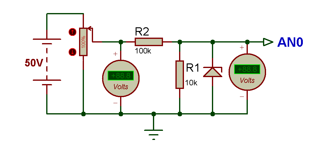
Arduino microcontroller equipped with 10-bit analogue to digital converter (ADC). This means Arduino can read 2^10=1024 discrete voltage levels.In this project, we measure the input voltage range between 0 to 50V by using the voltage divider. It is very simple to use Arduino as a voltmeter. Arduino UNO has 5 analog pin to read the input analog value. The circuit consists of two resistors, one LCD display and an Arduino which is brain of the digital voltmeter. The two resistor acts as voltage divider, the node of the divider is connected to analogue pin # A0 of the Arduino, which reads the input voltage. Ground connection is established between Arduino and external voltage source.
You cannot feed 50V directly to a Arduino I/O pin, you need a resistor divider network that converts 0-50V range into 0-5V.A 5.1V Zener diode in the figure is to prevent V_AN0 (V in) to rise above 5.1V if the input voltage goes much above 50V. This will protect the Arduino board.
The Arduino in built 10 bit ADC,can be used for measuring the 0Volt to 50 Volts Digital Voltmeter. LCD display connected with Arduino Uno will be used for displaying the measured voltage. This voltmeter can read only DC voltage.
Code Designing in Arduino IDE 1.8.0 :
So, here’s the programming code youneed to use for Displaying voltage value on LCD using Arduino board in Proteus ISIS:
#include "LiquidCrystal.h"

// initialize the library with the numbers of the interface pins

//            lcd(RS,  E, d4, d5, d6, d7)

LiquidCrystal lcd(2, 3, 4, 5, 6, 7);

float voltage = 0.0;

float V=0.0;

float R1 = 100000.0; // resistance of R1 (100K)

float R2 = 10000.0; // resistance of R2 (10K)

int analog_value= 0;

void setup()

{

Serial.begin(9600);

Serial.println("DIGITAL VOLTMETER");

lcd.begin(20, 4); // set up the LCD's number of columns and rows

lcd.setCursor (0,0);

lcd.print(" LET'S THINK BINARY "); // Print a message to the LCD.

lcd.setCursor (0,1);

lcd.print(" www.electronify.org "); // Print a message to the LCD.

lcd.setCursor(1,2);

lcd.print("Digital Voltmeter");

}

void loop()

{

// read the value at analog input pin A0

//and store it in the variable analog_value

analog_value = analogRead(A0);

voltage = (analog_value * 5.0) / 1024.0;

V = voltage / (R2/(R1+R2));

if (V < 0.1)

{

V = 0.0;//statement to quash undesired reading !

}

// Display the voltage in the serial monitor

Serial.print ("Voltage: ");

Serial.print (V);

Serial.println (" VOLTS");

// Display the voltage in the LCD

lcd.setCursor(0, 3);

lcd.print("Voltage= ");

lcd.print(V);

lcd.setCursor(15,3);

lcd.print("VOLTS");

// Wait 2 seconds between the measurements

delay (2000);

}
Digital voltmeter using Arduino UNO Range:0-50 volt Using SIMULINO UNO (Schematic Diagram)
Results :
Compile the Arduino code and get the hex file from it.
For simulating with PROTEUS ISIS hit run button and then you will get following results:

So, now we can see the LCD is displaying exactly the same values as are shown in the voltmeter. Now if you change the value of variable resistor then the value of voltage will change in LCD.
This digital voltmeter using Arduino UNO board can read voltage only between 0-50 volt.
DownloadHere
You candownload the Source Code and Proteus files etc from here arduino digital voltmeter:
This Our Group (thanks to join and participate) : https://www.facebook.com/groups/816450708460518/
Facebook page : https://www.facebook.com/Lets-Think-Binary-1728910547340654/
Youtube Channel (thanks to subscribe) :
https://www.youtube.com/channel/UCTIAzxEkyeA6HTvl_VHd-Tw
- What voltage range can this voltmeter read?
The proposed voltmeter design can read up to 50V DC. - How does the Arduino read the input voltage?
Arduino reads the input via its 10-bit ADC on analog pin A0 after the input is scaled by a voltage divider. - Can I feed 50V directly into the Arduino pin?
No, you cannot feed 50V directly; a resistor divider network is used to convert 0-50V to 0-5V. - What component protects the Arduino from voltages above 5V?
A 5.1V Zener diode is used to prevent V_IN from rising above 5.1V for protection. - What ADC resolution does the Arduino use in this project?
The Arduino uses a 10-bit ADC, giving 1024 discrete levels. - Where are the measured values displayed?
Measured voltage values are displayed on a 20x4 LCD and printed to the serial monitor. - Is this voltmeter suitable for AC measurements?
No, this voltmeter can read only DC voltage. - Which Arduino analog pin is used to read the divider node?
The node of the voltage divider is connected to analog pin A0. - What code environment is used for programming the Arduino?
Code is designed for the Arduino IDE (mentioned version 1.8.0) and used for Proteus simulation. - How often does the display update in the provided code?
The code delays 2000 milliseconds between measurements, updating every 2 seconds.