
Summary of Real Time Home Automation Using Arduino Uno R3 and DS1307 RTC (Part-1)
This article introduces Part 1 of an Arduino-based home automation project that controls appliances like fans and lamps on a schedule. It utilizes a DS1307 Real-Time Clock (RTC) to provide accurate time data to the Arduino Uno R3, which then triggers relays at specific times. The system displays current time on an LCD and includes code for setting automatic switch-on events based on the RTC's readings.
Parts used in the Real Time Home Automation Project:
- Arduino Uno R3
- DS1307 Real-Time Clock (RTC)
- Liquid Crystal Display (LCD)
- Relay modules
- 32.768Hz Crystal oscillator
- Battery backup supply
- NV SRAM memory
- I²C bus interface components
Hello every one , welcome back . In this new arduino tutorial series I’m gonna show you how to control every thing in your home on time basis . After doing this project you will be able to control your home appiliences like TV , Radio,Fan, and other thing on time basis . Let’s say you want to switch on TV exactly on 8 ‘O clock morning and fan on 12 PM and so on ,, This is on going series and will be updated if something new application is added on this project .
The concept of this project is very simple , DS1307 Real Time Clock sends Time,Date,and Day to the Arduino microcontroller , and according to the time set on code we can switch on relay to turn on LAMP,FAN etc .
Brief Introduction of DS1307
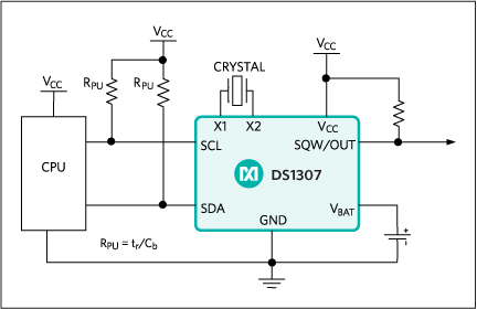
The DS1307 serial real-time clock (RTC) is a low-power, full binary-coded decimal (BCD) clock/calendar plus 56 bytes of NV SRAM. Address and data are transferred serially through an I²C, bidirectional bus. The clock/calendar provides seconds, minutes, hours, day, date, month, and year information. The end of the month date is automatically adjusted for months with fewer than 31 days, including corrections for leap year. The clock operates in either the 24-hour or 12-hour format with AM/PM indicator. The DS1307 has a built-in power-sense circuit that detects power failures and automatically switches to the backup supply. Timekeeping operation continues while the part operates from the backup supply. DS1307: Typical Operating Circuit DS1307: Typical Operating Circuit Enlarge+
Key Features
- Completely Manages All Timekeeping Functions
- Real-Time Clock Counts Seconds, Minutes, Hours, Date ofthe Month, Month, Day of the Week, and Year with Leap-Year Compensation Valid Up to 2100 A.D.
- 56-Byte, Battery-Backed, General-Purpose RAM with Unlimited Writes
- Programmable Square-Wave Output Signal
- Simple Serial Port Interfaces to Most Microcontrollers
- I2C Serial Interface
- Low Power Operation Extends Battery Backup Run Time
- Consumes Less than 500nA in Battery-Backup Mode with Oscillator Running
- Automatic Power-Fail Detect and Switch Circuitry
- 8-Pin DIP and 8-Pin SO Minimizes Required Space
- Optional Industrial Temperature Range: -40°C to +85°C Supports Operation in a Wide Range of Applications
Underwriters Laboratories® (UL) Recognized
note:crystal used in this project is 32.768Hz since it provide exact time to operate it on real time
you can buy this chip from this link
In the next part we will show you how to adjust time with push button . For now we are just setting time on code and everything will be control as exactly set on code . You can download complete project file with code , and proteus7simulation file from this link download project RTC home . And short description of the code and project is shown below the code .
Real Time Home Automation Using Arduino Uno R3 and DS1307 RTC (Part-1) Code
//created by prasant

//all right reserved to electronify.org

//you can copy edit or do what ever with  this code

#include

#include "RTClib.h"

#include

LiquidCrystal lcd(12, 13, 8, 9, 10, 11);

RTC_DS1307 RTC;

void setup () {

Wire.begin();

RTC.begin();

lcd.begin(20, 4);

pinMode(7,OUTPUT);

pinMode(6,OUTPUT);

// following line sets the RTC to the date & time this sketch was compiled

RTC.adjust(DateTime(__DATE__, __TIME__));

}

void loop () {

DateTime now = RTC.now();

lcd.setCursor(0, 0);

lcd.print(now.day(), DEC);

lcd.print('/');

lcd.print(now.month(), DEC);

lcd.print('/');

lcd.print(now.year(), DEC);

lcd.print(' ');

lcd.setCursor(0, 1);

if (now.hour()<10)

lcd.print('0');

lcd.print(now.hour(), DEC);

lcd.print(':');

if (now.minute()<10)

lcd.print('0');

lcd.print(now.minute(), DEC);

lcd.print(':');

if (now.second()<10) lcd.print('0'); lcd.print(now.second(), DEC); if ( ( now.hour() == 12 ) && ( now.minute() == 20 ) ) { digitalWrite(7,HIGH); lcd.setCursor(0, 2); lcd.print("TM:12:20 MOTOR IS ON"); } else { digitalWrite(7,LOW); lcd.setCursor(0, 2); lcd.print("MOTOR TM 12:20-12:21"); } if ( ( now.hour() == 12 ) && ( now.minute() > 20 )&& ( now.minute() <= 25 ) )

{

digitalWrite(6,HIGH);

lcd.setCursor(0, 3);

lcd.print("TM :12:20 LAMP IS ON");

}

else

{

digitalWrite(6,LOW);

lcd.setCursor(0, 3);

lcd.print("LAMP TM 12:20-12:25");

}

delay(50);

}
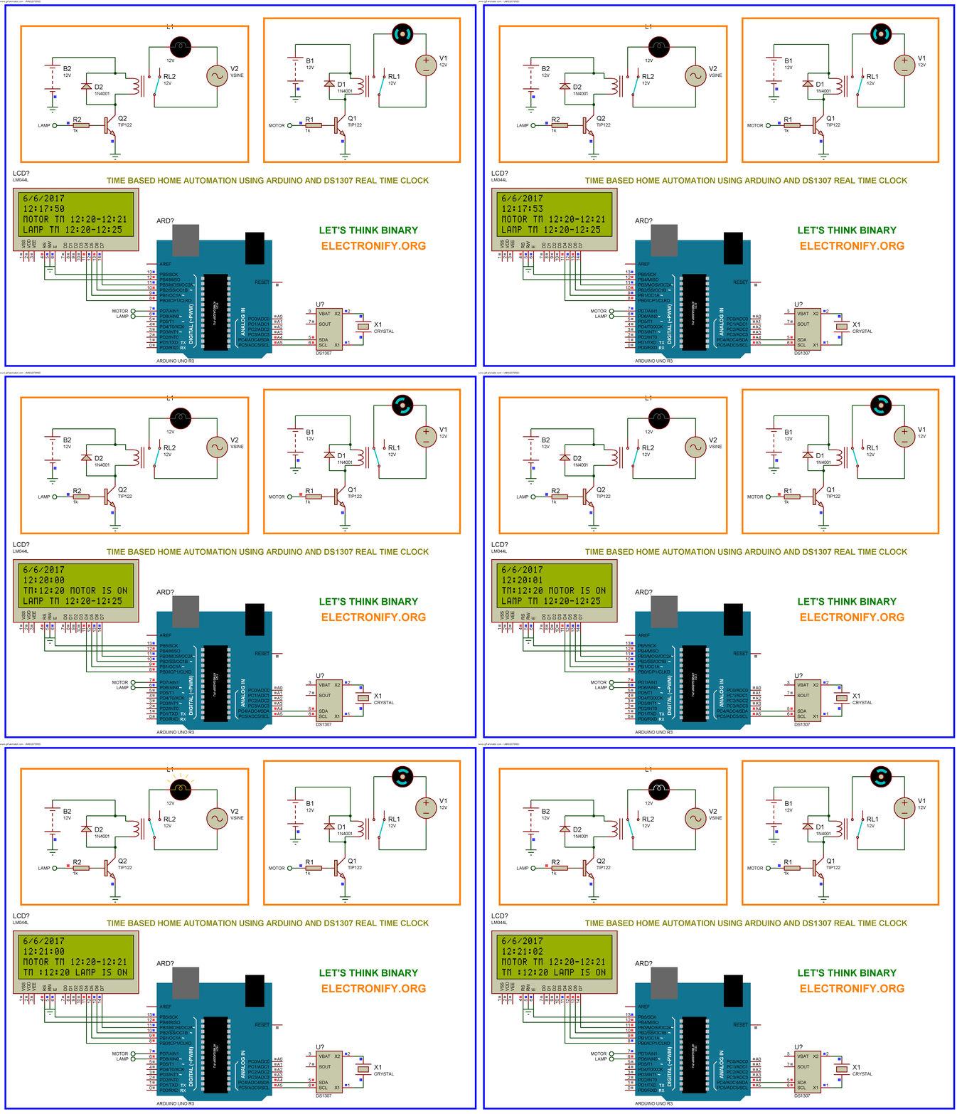
Real Time Home Automation Using Arduino Uno R3 and DS1307 RTC (Part-1) Schematic Diagram
Short Description
Yeah! the code is very simple to understand ,because it’s arduino code . Arduino code generally have lot’s of ready made library ,so its easy to use them provided with their documentation and without these library programming is very complex. So let’s talk about the code .First we have included RTClib and Wire library . You can download these two library from this link real time home automation library . Wire library is used for TWI interface , and RTClib library is used to receive real time data from the real time clock chip . ( if you want to learn about TWI or I2C feature of AVR chip go to this link and more information like register etc about real time clock in this link . )
After including the libraries what I have did is initialize LCD and also pinMode for relays output . Then after inside never ending loop we get time using structure we have created now . Using now.day() function we get day value , using now.year() we get year value , and now.hour() we get hour value and so on ,, and coverted these different value with appropriate representation and then displayed on LCD .
To make automatic switch we have defined value of time (hour, minute , second ) on the if statement and if time reached that point Arduino automatically send HIGH on that perticular pin . That’s it .
If you did not understand what i exactly mean , please leave a comment below , i will try to solve your question . keep learning and if you found this information useful please share this on your time line .
-
What is the main function of the DS1307 chip in this project?
The DS1307 sends time, date, and day information to the Arduino microcontroller to enable scheduled control of appliances. -
How does the system handle power failures?
The DS1307 has a built-in power-sense circuit that detects power failures and automatically switches to a backup supply to continue timekeeping. -
Which crystal frequency is required for exact real-time operation?
A 32.768Hz crystal is used because it provides the exact time needed to operate the project on a real-time basis. -
Can the DS1307 operate in both 12-hour and 24-hour formats?
Yes, the clock operates in either the 24-hour or 12-hour format with an AM/PM indicator. -
How are specific appliances turned on automatically in the code?
The code uses if statements to check the current hour and minute; when the set time is reached, the Arduino sends a HIGH signal to the specific pin connected to the appliance. -
What libraries are included in the provided Arduino code?
The code includes the Wire library for the TWI interface and the RTClib library to receive real-time data from the clock chip. -
Does the DS1307 automatically adjust for leap years?
Yes, the clock/calendar includes corrections for leap year and adjusts the end of the month date for months with fewer than 31 days. -
How much RAM does the DS1307 contain for general-purpose use?
The chip contains 56 bytes of battery-backed NV SRAM with unlimited writes.
