
Summary of IN-12 nixie clock
This article details a simple, low-cost nixie clock project using a single IN-12A tube and a PIC16F84A microcontroller. Designed for budget-conscious builders, it avoids complex driving circuits and custom power supplies by utilizing discrete transistors and repurposed camera components for high voltage. The author provides schematic files and code, opting to design a PCB for better aesthetics compared to the original Veroboard version.
Parts used in the IN-12 Nixie Clock:
- PIC16F84A microcontroller
- IN-12A nixie tube (or B variant)
- Discrete transistors
- High voltage supply components from a disposable camera
- Push button
- PCB (Printed Circuit Board)
- Schematic and code files
Ever since I discovered nixies I wanted to make a clock with them, but all the designs I found were for 4 or more nixies, required a custom power supply and a complicated driving system.
As the cheap guy I am, I didn’t want to buy lots of nixies or components to make such complicated circuits. And after ages looking for a simple clock design I came up with this page.
This clock uses a single chip which I’ve already used before, the PIC16F84A. The circuit is also pretty simple since it uses a single nixie, driven by discrete transistors and doesn’t need a powerful HV supply.
In the page only the schematic and code are provided because this guy builds his circuits on Veroboard, But I wanted to make a good-looking clock so I decided to design and make a PCB.
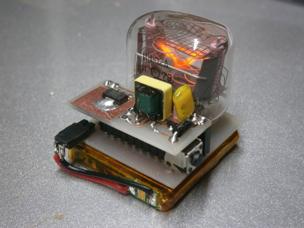
The tube I’ve used is an IN-12A, but a B variant can be used as well (or any other nixie tube with the proper circuit modifications). The high voltage supply uses components from a disposable camera, so it also costs almost nothing.
The clock displays the time periodically flashing the digits from tens of hours to minutes.
To set the time you have to push the button when the digit you want to change is being displayed, it will increase each time you push and cycle from 0-9.
If you hold down the button during power on, the clock will rapidly cycle trough the digits. It is useful to kill off some “cathode poisoning” on nixies that have not been used in a while.
Step 1: The main board
The main board contains all the components except the high voltage power supply, so anyone can build a different HV circuit without changing this board.
The .brd and .sch files are available so you can modify the circuit as you please
The PDF file is linked down so you can make your own PCB.
For more detail: IN-12 nixie clock
- How is the time set on the clock?
Push the button when the specific digit you want to change is displayed; each press increases the value cycling from 0 to 9. - Can I use a different nixie tube?
Yes, a B variant or any other nixie tube can be used with proper circuit modifications. - What is the best way to source the high voltage supply?
The design uses components from a disposable camera to keep costs near zero. - Does this project require a custom power supply?
No, it does not need a powerful HV supply or a complicated driving system. - How do I kill off cathode poisoning on unused nixies?
Hold down the button during power on to rapidly cycle through the digits. - Is the circuit built on Veroboard?
The original design used Veroboard, but this project features a designed PCB for better looks. - What components are needed to build the main board?
All components except the high voltage power supply are included on the main board. - Can I modify the circuit design?
Yes, .brd and .sch files are available for modification.