Summary of Better SPI Bus Design in 3 Steps
This article outlines three critical improvements for robust Arduino SPI bus designs to prevent device conflicts. It emphasizes using pullup resistors on chip select and reset lines, verifying tri-state behavior on the MISO line (using buffers if needed), and protecting bus access with `SPI.beginTransaction()` and `SPI.endTransaction()`. The text provides a code snippet to manually set chip select pins high during setup as a workaround for shields lacking hardware pullups.
Parts used in the Better SPI Bus Design:
- Pullup resistors
- Tri-state buffer chip
- SPI library functions (beginTransaction, endTransaction)
- Arduino microcontroller
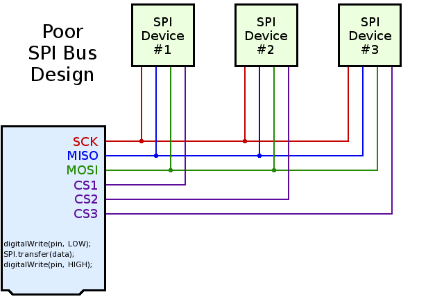
Most Arduino SPI tutorials show this simple but poor SPI bus design:
A much better SPI bus design can prevent conflicts. 3 simple improvements are needed:
-
Use pullup resistors on all chip select signals.
-
Verify tri-state behavior on MISO: use a tri-state buffer chip if necessary.
-
Protect bus access with SPI.beginTransaction(settings) and SPI.endTransaction().
Click “Read more” for details on these 3 steps.
Step 1: Pullup Resistors for Chip Select & Reset Signals
When multiple SPI devices are used, and especially when each is supported by its own library, pullup resistors are needed on the chip select pins.
Without a pullup resistor, the second device can “hear” and respond to the communication taking place on the first device, if that second device’s chip select pin is not pulled up. This is easy to understand in hindsight, but it can be temendously confusing and frustrating to novice Arduino users who purchase shields or breakout boards without pullup resistors. Each SPI device works when used alone, but they sometimes mysteriously fail when used together, only because both devices are hearing communication meant to initialize only the first device!
A simpe workaround for devices without pullup resistor involves adding code at the beginning of setup.
    void setup() {
      pinMode(4, OUTPUT);
      digitalWrite(4, HIGH);
      pinMode(10, OUTPUT);
      digitalWrite(10, HIGH);
      delay(1);
      // now it's safe to use SD.begin(4) and Ethernet.begin()
    }
For more detail: Better SPI Bus Design in 3 Steps
- Why are pullup resistors needed on chip select signals?
Pullup resistors prevent multiple devices from hearing and responding to communication meant for only one device. - What happens if a second SPI device lacks a pullup resistor?
The second device may respond to initialization commands intended for the first device, causing mysterious failures. - How can you work around missing pullup resistors in code?
Add code to set the chip select pin to HIGH in the setup function before initializing other libraries. - When should you use a tri-state buffer chip?
Use a tri-state buffer chip if you need to verify tri-state behavior on the MISO line. - Which functions protect SPI bus access?
Use SPI.beginTransaction(settings) and SPI.endTransaction() to protect bus access. - Why do SPI devices sometimes fail when used together?
They fail because both devices hear communication meant to initialize only the first device due to floating chip select pins.