
Summary of Custom OBD II Gauge in With OEM Look
The author built an Arduino-based custom OBD-II gauge to replace the OEM clock in a Subaru BRZ/FRS, sharing open-source code and instructions for others to replicate or adapt it. The project uses an Arduino, an OBD interface, and a monochrome OLED to display vehicle diagnostics, with optional analog sensors and detailed tooling, libraries, and software recommendations provided.
Parts used in the Custom OBD II Gauge:
- Arduino or Arduino clone (Adafruit Pro Trinket recommended)
- STN1110/ELM327 OBD-II board (Sparkfun recommended)
- Assorted hookup wire
- 128x32 SPI monochrome OLED display (Adafruit recommended)
- OEM clock (Scion FRS/BRZ clock used)
- Some resistors (for button setup)
- Optional analog sensors (Autometer oil temp, Autometer oil pressure, accelerometer, pressure, temperature)
https://github.com/stirobot/arduinoModularTFTgaugesI built a custom OBD II (on board diagnostics version 2 http://en.wikipedia.org/wiki/On-board_diagnostics) gauge in the clock of my Subaru BRZ (GT86, FRS) and a lot of people wanted me to build them one. Here is how you can build one of your own. My wife is about to give birth to our second son and all the code is open source, so I have nothing to lose by posting this.
(I still may sell the installation as a service or possibly the packaging of a kit in the future, but that won’t prevent others from using the open source pieces to do what they want in their own installations, other cars, other displays, etc. and frankly there is no money to be had in this. So, I’d rather share it with the DIY community at large.)
I’ll try to point out where I did things that are specific to my model of car and where you might want to change things to suit your needs. Hopefully this will allow others to build on what I’ve done.
The all important github link:https://github.com/stirobot/arduinoModularTFTgauges/blob/master/oledOBDgaugesSmallIrvinedLib.ino
And more generically my code is here: https://github.com/stirobot/arduinoModularTFTgauges
The car specific forum where all of this is getting discussed: http://www.ft86club.com/forums/showthread.php?p=1967204#post1967204
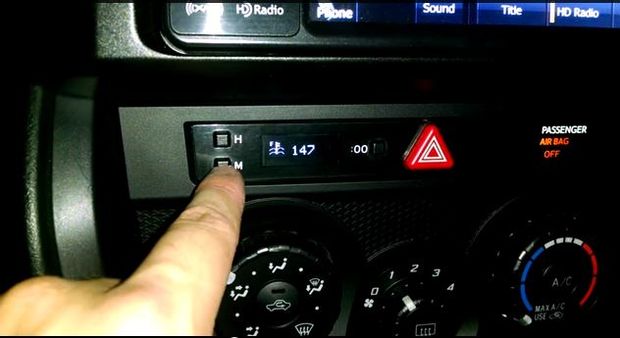
Step 1: What you will need to do this (parts/tools/software/etc)
Parts (generic/specific):
-An Arduino or Arduino clone – I specifically use the adafruit pro-trinket for its small form factor and 5v logic.https://www.adafruit.com/products/2000
-STN1110/ELM327 board. I chose the Sparkfun one because it is stable, uses UART for communication and doesn’t cost and arm and a leg. https://www.sparkfun.com/products/9555
-Assorted hookup wire
-128×32 SPI monochrome OLED display. I used the adafruit one. The ebay ones may work just as well, but I haven’t tested them.
-Your OEM clock. I used the OEM clock from a Scion FRS that I got on ebay.
-Some resistors (for the button setup)
-Optional – sensors (autometer oil temp, autometer oil pressure, acceleromter, pressure, temperature). I have some arduino code that will let you plug analog sensors into a system like this. I’ll make one of the “steps” pages about this.
Tools:
-Soldering Iron
-Wire stripers
-Wire crimpers
-Helping hands
-scissors
-dremel tool
Code libraries used:
-Arduino ELM327 library: https://www.clusterfsck.io/blog/2014/05/23/arduino-elm327-library/ . I thrashed around with the UART comms to the OBD II board for a long time. (you can see it in my crummy code for the 1.8” TFT version of this). This saved my project and my sanity.
-The Adafruit libraries for the OLED screen and tutorials: https://learn.adafruit.com/monochrome-oled-breakouts I love supporting this vendor as they always provide a lot of extras when you buy from them (support, working code (emphasis on working), tutorials, etc.)
Software:
Sublime Text2 Stino plugin (because real syntax highlighting is refreshing) – http://robot-will.github.io/Stino/
the dot factory – for making monochrome bitmaps into arrays so you can display them on the screen (That’s how I got my icons)
windows paint – for drawing icons and splash screens
For more detail: Custom OBD II Gauge in With OEM Look
- What microcontroller is recommended for this project?
The author specifically uses the Adafruit Pro Trinket for its small form factor and 5V logic. - Which OBD-II interface board does the project use?
The project uses an STN1110/ELM327 board; the author chose the Sparkfun version. - What display is used for the gauges?
A 128x32 SPI monochrome OLED display is used; the author used the Adafruit one. - Can I use my car's OEM clock for this installation?
Yes; the author used the OEM clock from a Scion FRS/BRZ obtained on eBay. - Are there optional sensors supported by the code?
Yes; the author mentions optional analog sensors like Autometer oil temp and pressure, accelerometer, and other sensors with supporting Arduino code. - What libraries are recommended for OBD communication?
The Arduino ELM327 library referenced at clusterfsck.io is recommended for UART comms to the OBD-II board. - What libraries are recommended for the OLED display?
The Adafruit libraries and tutorials for monochrome OLED breakouts are recommended. - What tools are needed to build and install this gauge?
Tools listed include a soldering iron, wire strippers, wire crimpers, helping hands, scissors, and a dremel tool. - What software was used for development and assets?
Sublime Text2 with the Stino plugin, the dot factory for bitmaps, and Windows Paint for icon design are used. - Where is the project code hosted?
The code is open source on GitHub at stirobot/arduinoModularTFTgauges with a specific sketch for the OBD gauges.
