
Summary of Tri-State Logic
Summary: This project demonstrates using the Arduino pin's third state (input) plus diodes to control two LEDs with a single pin. By setting the pin HIGH or LOW one LED lights, rapidly toggling replicates both on via persistence of vision, and setting the pin to INPUT turns both off. Diodes drop voltage and resistors limit current; only one resistor is strictly necessary.
Parts used in the One-pin two-LED project:
- 4 x Diodes
- 2 x LEDs
- 2 x 330 Ohm Resistors
- Jumper Wires
- Arduino (implied for pin control)
Introduction
So far we have sent one of two values to any Arduino output pin, either HIGH or LOW. This project shows how we can exploit a third state of the Arduino pins to reduce the number of pins needed to control LEDs. In the project, we’ll control 2 LEDs using only one Arduino pin.
You Will Need
- 4 x Diodes
- 2 x LEDs
- 2 x 330 Ohm Resistors
- Jumper Wires
Diodes have to be the correct way around to function. Current passes through the diode in the direction of the thin black line on the diode.
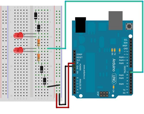
Making The Circuit
The following diagram shows how to wire this circuit.
The following diagram shows the schematic for the circuit, which may help you to understand how this process works,
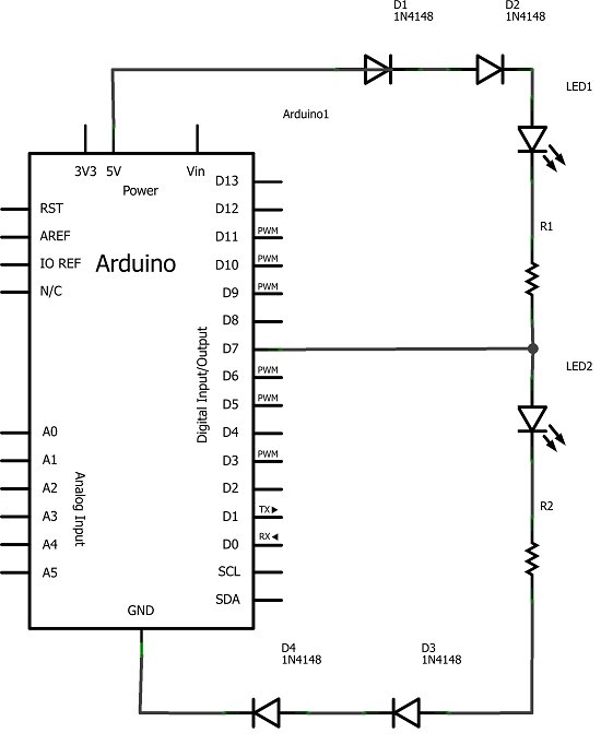
If pin 7 is set to output LOW, LED 1 is lit. If pin 7 is set to output HIGH, there is no drop in voltage across the first LED and so only the second LED is lit. By rapidly switching the output from HIGH to LOW, both pins appear to be lit at the same time. This is due to the what is commonly referred to as the persistence of vision effect. There are some myths about how and why this effect occurs and several explanations are possible. Regardless, if the switching is quick enough, it looks like both LEDs are on at the same time. In order to switch both of the LEDs off, pin 7 is turned into an input pin.
The diodes in this circuit are used to drop the voltage in the circuit, if only 2 are used (one at each end of the circuit), the LEDs remain dimly lit. Although there are 2 resistors in the circuit, only one is needed since the LEDs are never actually on at the same time.
Programming The Arduino
The following sketch contains the code needed to turn each LED on individually, both at the same time, and to turn them both off,
int tripin = 7;

void setup()
{
pinMode(tripin, OUTPUT);
}


void loop()
{
pinMode(tripin, OUTPUT);
digitalWrite(tripin, HIGH);
delay(1000);
digitalWrite(tripin, LOW);
delay(1000);
bothOn();
bothOff();
delay(1000);
}

void bothOn()
{
for (int i =0;i<1000;i++)
{
digitalWrite(tripin, HIGH);
delay(1);
digitalWrite(tripin, LOW);
delay(1);
}

}

void bothOff()
{

pinMode(tripin, INPUT);
}
For more detail: Tri-State Logic
- What is the goal of this project?
To control 2 LEDs using only one Arduino pin by exploiting the pin's third state. - How do you light LED 1?
Set pin 7 to output LOW to light LED 1. - How do you light LED 2?
Set pin 7 to output HIGH to light LED 2. - How do you make both LEDs appear lit at the same time?
Rapidly switch the pin between HIGH and LOW so persistence of vision makes both appear on. - How do you turn both LEDs off?
Change pin 7 to an input to turn both LEDs off. - Why are diodes used in this circuit?
Diodes are used to drop voltage in the circuit so the LEDs behave as intended; using only two diodes leaves LEDs dimly lit. - Are both resistors required?
Although two resistors are shown, only one is needed since the LEDs are never actually on at the same time. - What sketch functions are used to make both LEDs appear on?
The sketch uses a bothOn function that rapidly toggles the pin HIGH and LOW in a loop to create the effect.