
Summary of Power your Arduino with a Hand-Cranked Battery
This article describes a DIY project to create a portable, rechargeable power source for Arduino and AVR development boards using a modified hand-cranked flashlight. The setup generates approximately 3.5V, sufficient for various microcontrollers like ATtiny, ATmega, and STM32F. By cranking the handle periodically, users can avoid battery replacements and operate devices without wall outlets or USB connections, making it ideal for mobile testing or field use.
Parts used in the Hand-Cranked Power Source:
- DC motor
- Small lithium battery (3.3V capacity)
- Diode (1N4148)
- Crank mechanism components (rod, hot glue, rubber band, or pre-made flashlight case)
- Wire and wire snips
- Soldering iron
- Slide switch
- 3.3V zener diode (optional voltage regulator)
- Bypass capacitors
If you’ve ever wanted to power your Arduino or AVR from a battery for development testing (batteries have different power delivery qualities than, say, transformed AC or even a regulated wall wart in DC) testing but were tired of going through batteries (Hey, I admit I’ve sucked batteries dry in hours because of a slipped-up design before I caught it).
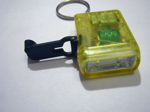
Maybe you want to take your design and project mobile, for instance, up in the mountains away from your vehicle and any plug in outlets. It might be useful to have a battery powered device whose batteries you never change, but just crank up once a week. Or better yet, maybe you want to take your Arduino to the coffee shop and not have to look for an outlet or USB connection. Well, here’s a quick little way to power your development board from a battery that never (well, you know) runs out.
I’ve taken a hand-crank-powered flashlight and hax0red it to power my AVR and Arduino development boards. The battery lasts for a good long time and if you crank it a few times before you use it you’ll find you’ll get a solid 3.5V out of it (depending on your battery). Plenty enough to power an AVR ATtiny, ATmega, and ATxmega, as well as other 3.3V devices like the STM32F ARM MCU indefinitely!
Step 1: Necessary Items
To make this work, you’ll need either:
- DC motor (I’ve tried about 3 or 4 different kinds of DC motors for this and I got them all out of old CD/DVD players so you don’t have to pay for one if you cannibalize).
- small 3.3 or whatever capacity battery (I’ve used several small lithiums for my testing)
- diode (a small 1N4148 will do)
- something to make a crank with (rod & hot glue, rubber band, etc)
or you can buy a hand-cranked flashlight from ebay for a buck and change. This method is prefereable for a couple of reasons. First, the cranking mechanism is far superior to probably anything you’re going to make and will really torque up when you crank it, delivering energy to the battery and straight on through to the powered device. Second, you’ll have a tiny motor and small battery already included for probably what you’d end up paying for the battery alone, so splurge and buy one or two (I bought two) hand-cranked flashlights. You’ll be glad you did.
For both versions you’ll need the standard tools: wire, wire snips, soldering iron, etc.
Step 2: Get out the good bits
If you are building from scratch, skip this step.
Unscrew the handcranked torch case screws. Pull out the chrome plastic reflector and two low-voltage white LED’s. They will be soldered in parallel and to the battery. Unsolder or otherwise heat up the solder joints and gently pull the LED structure away from the case components.
Now you have a case with a hand crank, a motor and a battery connected via a diode. Check out the schematic on the next page for how it all fits together.
Step 3: Solder connections
(-) Motor (+) ---> Diode ---> (+) Battery ---> Leads
 |
 |---> (-) Battery ---> Switch ---------------> Leads
The motor is connected to the positive terminal of the battery via a diode that manages back EMF when the motor is suddenly stopped (ie you stop cranking). A small switching diode like the 1N4148 works well for this tiny amount of voltage and current we’ll be seeing. Attach a long wire/lead from the positive terminal of the battery.
The negative terminal of the motor is attached to the negative terminal of the battery and next a slide switch is soldered on to conserve energy/power when the battery is not in use. Sure, we can wind it up and recharge a bazillion times, but why when we don’t have to? Attach a long wire or lead from the “on” end of the slide switch.
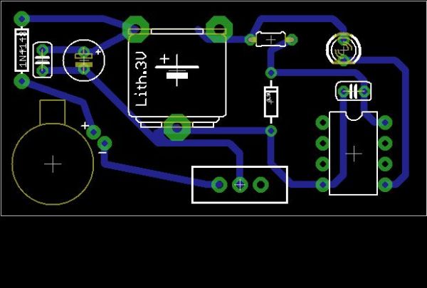
The schematics show a test setup with a motor and all requirements built in. You can build this on a bread board for your tests or you can power some other board that you may already have, as I did with my ATtiny Stick Development Board that I built myself. I also use a 3.3V zener as a voltage regulator “just in case,” to protect the AVR. As always, bypass caps from Vcc to GND on all AVRs.
 crank v1.0.brd11 KBcrank v1.0.sch247 KB
- DC motor
- small battery
- diode
-
How does this project power an Arduino board?
The device uses a DC motor connected to a battery via a diode; cranking the handle generates energy that charges the battery and powers the board directly. -
Can I build this from scratch instead of buying a flashlight?
Yes, you can construct it using a DC motor salvaged from old CD/DVD players, a small battery, a diode, and materials to make a crank. -
What voltage output does the hand-cranked system provide?
Cranking the handle produces a solid 3.5V output depending on the battery, which is enough to power 3.3V devices indefinitely. -
Why is a diode necessary in the circuit?
A small switching diode like the 1N4148 manages back EMF when the motor is suddenly stopped while cranking. -
Which microcontrollers are compatible with this power source?
The setup works with AVR ATtiny, ATmega, and ATxmega chips, as well as 3.3V devices like the STM32F ARM MCU. -
What is the purpose of the slide switch in the design?
The slide switch is soldered to the negative terminal to conserve energy by disconnecting the load when the battery is not in use. -
Is a voltage regulator required for the AVR?
A 3.3V zener diode can be added as a voltage regulator just in case to protect the AVR, though bypass caps are always recommended. -
Where can I find the DC motor for this project?
You can obtain a suitable DC motor by cannibalizing old CD/DVD players or by purchasing a cheap hand-cranked flashlight from eBay.
