Summary of AVR Programming Tutorial
This tutorial teaches AVR microcontroller programming using the ATmega328p (as on Arduino) with plain AVR C. It covers toolchain installation, required materials, programmer options (Arduino as ISP, AVRISP mkII, USBtiny/FabISP), powering the chip, connecting and verifying via avrdude, common errors, and a basic LED circuit example. It aims to demystify Arduino, enable use of smaller AVRs, and improve low-level control for performance-sensitive projects.
Parts used in the AVR Programming Tutorial:
- ATmega328p
- Arduino Duemilanove (with ATmega328) or other Arduino board (optional, for ISP)
- AVRISP mkII (optional programmer)
- USBTinyISP or FabISP (optional programmer)
- Breadboard
- 10K resistor (pull-up for reset)
- 330Ω resistor (for LED)
- LED (e.g. 5mm)
- Jumpers and/or wire
- 9V battery and 7805 voltage regulator (for AVRISP mkII power example)
- 0.1 uF capacitor (for regulator)
This tutorial introduces programming for AVR microcontrollers. It uses the ATmega328p found on Arduino boards, but works with straight AVR C and a bare microcontroller. It covers the basic information you need to get started, whether or not you’ve used Arduino or other microcontrollers previously.
Why would you want to learn AVR programming (instead of, say, using Arduino)? First, it should demystify what happens inside of the Arduino platform (which is really fairly simple). Second, it will give you the flexibility to use other microcontrollers, like the ATtiny series, which are smaller and cheaper than the ATmega328. Third, it will help you take full advantage of the microcontroller’s capabilities, which can be important when writing performance-critical applications.
AVR Toolchain
Download and install:
Examples
Download the examples: avr-examples.zip
Materials
You’ll need the following:
- an AVR in-system programmer, e.g. one of the following:
- Arduino Duemilanove (w/ ATmega328, not ATmega168)
- AVRISP mkII
- USBTinyISP
- FabISP
- ATmega328p
- Breadboard
- 10K resistor
- 330Ω resistor
- LED (e.g. 5mm)
- Jumpers and/or wire
For more information, see our list of materials and parts and our list of prototyping supplies.
Microcontroller (ATmega328p)
We’re using the ATmega328p microcontroller. You’ll want to download the datasheet. Here’s the pinout of the DIP (through-hole) package. The pins are numbered on the inside and labelled on the outside. In parentheses are abbreviations for some of the unique functions of each pin.
Connect your Programmer
To load programmers onto the ATmega328p, you need an in-system programmer (ISP). There are a few of these, each with slight differences.
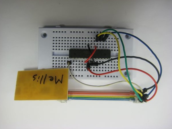
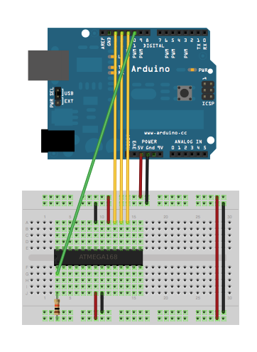
Using an Arduino as an ISP
Connecting the Arduino and ATmega328
Here, we’re using the Arduino board to program the ATmega328 as well as supply power to it. Notice we only need a single component besides the microcontroller: the 10K resistor (brown, black, orange) pulling the reset line high.
Turning your Arduino into an AVR In-System Programmer
Arduino 0018 (download) comes with a firmware (sketch) that turns your Arduino board into an AVR in-system programmer, allowing you to upload programs onto other microcontrollers. To use it, upload the ArduinoISP example to your Arduino.
AVRISP mkII
If you want to use an AVRISP mkII, you’ll need to provide power separately. Here we use a 9V battery and a voltage regulator to bring this down to five volts.
Insert the 7805 voltage regulator into your breadboard, and add an 0.1 uF capacitor across the output and ground pins.
Attach a battery and use a multimeter to confirm that the regulator is producing ~5V output.
Add the microcontroller to the setup, and make sure that all of the GND and VCC pins are connected properly.
Attach:Microcontroller_added.jpg Δ Δ
Here’s the pinout for the AVR ISP connector. Remember that the red wire in the ribbon cable indicated pin 1, and that this diagram shows the connections as viewed from the back of the connector, i.e. if you’re looking at the holes, this diagram is reversed..
If you are using the 7805 regulator to power your microcontroller and the AVRISPmkII to program it, your completed setup (including 10k pullup resistor on the reset pin) should look something like this. Notice that the status light on the programmer turns green when everything is connected properly. If is flashes yellow, one or more of your connections may be wrong. If the light turns red, check your power supply.
Attach:Completed_setup.jpg Δ Δ
FabISP
Verifying the Circuit and Software
To check that your software installation is working and your circuit is correct, you’ll need to run a command in a command prompt (or “terminal”). To open a command prompt, run:
- Mac OS X: Terminal (in Applications > Utilities)
- Windows:
cmdfrom the run option in the Start menu - Linux: look for something called “terminal” or “xterm”
Once at a command prompt, run the following command:
- Arduino as ISP:
avrdude -p m328p -c stk500v1 -b 19200 -P <PORT>, where<PORT>is:- Mac OS X:
/dev/tty.usbserial-* - Windows:
COM3, for example; use the COM port that your Arduino board is on - Linux:
/dev/ttyUSB0
- Mac OS X:
- AVRISP mkII:
avrdude -p m328p -c avrisp2 -P usb - FabISP:
avrdude -p m328p -c usbtiny
You should get:
Reading | ################################################## | 100% 0.01s

avrdude: Device signature = 0x1e950f

avrdude: safemode: Fuses OK

avrdude done.  Thank you.
which means that the avrdude has talked to your ISP, the ISP has talked to the chip, the chip has reported its device signature (here 0x1e950f ) back to the ISP, which passed it on to avrdude, which confirmed that it matched the device signature of the microcontroller you specified in the -c parameter (the ATmega328p).
Possible errors:
avrdude: ser_open(): can't open device "/dev/tty.usbserial-*": No such file or directory
- Is your Arduino board connected? Is the power LED on?
avrdude: stk500_recv(): programmer is not responding
- Does the ATmega328p have power? Is it wired correctly? Did you upload the ArduinoISP sketch to your Arduino board?
avrdude: AVR device initialized and ready to accept instructions

Reading | ################################################## | 100% 0.13s

avrdude: Device signature !!0x000000
avrdude: Yikes!  Invalid device signature.
         Double check connections and try again, or use -F to override
         this check.
- Is the ATmega328 connected to the Arduino correctly?
avrdude: ser_open(): can't open device "\\.\COM3": The system cannot find the file specified.
- Did you use the right COM port? (Windows)
avrdude
The program avrdude lets you upload compiled programs (hex files) to your microcontroller. (It’s what the Arduino development environment uses to upload sketches to the Arduino board.) You run it from the command line, with various parameters:
-p part
Specifies the microcontroller (part) you’re programming, e.g. atmega328p
-P port
The port you’re uploading to. If you are using an Arduino board as a programmer, this will be something like /dev/tty.usbserial-A6008b1a on the Mac (or you can just use /dev/tty.usbserial-* to select it automatically). On Windows, it’s COM or similar (you can check in the Device Manager). On Linux, it’s probably /dev/ttyUSB0. If you’re using an AVRISP mkII, it will be usb instead on all three operating systems. For a USBtinyISP or a FabISP, you omit this parameter entirely.
-c protocol
The protocol to use for uploading. If using an Arduino board as a programmer, this should be stk500v1. For an AVRISP mkII, avrisp2. For the FabISP or a USBtinyISP, it’s usbtiny.
-b baud rate
The baud rate to use for uploading. For an Arduino as programmer, use 19200. If using an AVRISP mkII, USBtinyISP, or FabISP, this parameter can be omitted altogether.
Connecting an LED
Now that you’ve got the basic circuit working, let’s hook up an LED so we can see the microcontroller do something. Connect the longer leg of the LED to pin PB0 (pin 14 of the ATmega328p), and the shorter leg goes through a 330Ω (orange orange brown) resistor to ground. If you look carefully at the LED, you’ll notice that one side of it is flat – the leg on that side goes to ground.
For more detail: AVR Programming Tutorial
- How do I install the AVR toolchain on my OS?
Install CrossPack on Mac OS X, WinAVR on Windows, and gcc-avr, avr-libc, avrdude packages on Linux. - Can I use an Arduino as an ISP to program the ATmega328p?
Yes; upload the ArduinoISP example sketch (Arduino 0018 includes it) to the Arduino and connect it to the ATmega328p, using a 10K pull-up on reset. - What programmers are supported for programming the ATmega328p?
Arduino as ISP (stk500v1), AVRISP mkII (avrisp2), USBtinyISP or FabISP (usbtiny) are described. - How do I verify the circuit and software are working?
Run avrdude with the appropriate parameters for your programmer and part; a successful run shows Device signature and Fuses OK messages. - What common avrdude errors might I encounter and why?
Errors include can't open device (Arduino not connected), programmer not responding (power/wiring or ArduinoISP not uploaded), invalid device signature (wrong connections), and wrong COM port on Windows. - How should I power the ATmega328p when using an AVRISP mkII?
Provide external power, e.g. a 9V battery and a 7805 regulator to produce ~5V, with proper capacitors and verify with a multimeter. - What avrdude parameters are important to set?
Use -p to specify part (m328p), -P for port (or usb/omit for USBtiny), -c for protocol (stk500v1, avrisp2, usbtiny), and -b for baud (19200 for Arduino as ISP). - How do I connect an LED to the ATmega328p for testing?
Connect the LED long leg to PB0 (pin 14) and the short leg through a 330Ω resistor to ground; the flat side of the LED is the ground side.