
Summary of Arduino Knight Rider
This tutorial guides users in interfacing eight LEDs with an Arduino Uno to create a "Knight Rider" display effect. It assumes prior knowledge from Tutorial 3 and details the necessary components, including resistors and wire links. The project involves connecting LED anodes to Arduino pins 2 through 9 and cathodes to ground via resistors on a breadboard. A specific program is loaded to animate the lights sequentially.
Parts used in the Arduino Knight Rider Display:
- Breadboard
- Arduino Uno board
- USB cable
- 470 ohm resistor (8 units)
- 5mm red LED (8 units)
- Wire links (9 units)
In this tutorial, eight LEDs are interfaced to the Arduino Uno board. This is not complicated – it is just like interfacing a single LED to the Arduino as done in tutorial 3, but eight times over. A program is then loaded to the Arduino that will turn the eight LEDs into a “Knight rider” display.
The following video shows what you will achieve:
Can’t see the video? View on YouTube →
Prerequisites
You will need to have completed tutorial 3 and its prerequisites before attempting this tutorial.
Components
Besides a breadboard, Arduino Uno and USB cable, you will need:
| Qty | Part | Designator | Notes | Type |
|---|---|---|---|---|
| 8 | 470 ohm resistor (yellow – violet – brown) | R1 | 1/4W, 5% or better | Resistors |
| 8 | 5mm red LED | D1 | Other coloured and sized LEDs could also be used, e.g. 3mm green LED | Semiconductors |
| 9 | Wire links | Wire links that will reach from the breadboard to the Arduino | Wire |
Circuit Diagram
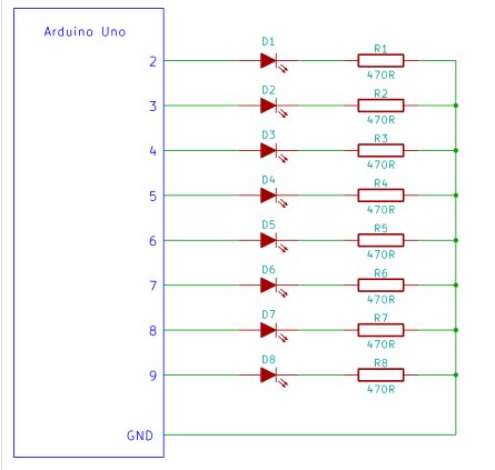
The circuit diagram is shown below. It is simply eight LEDs interfaced to the Arduino pins 2 to 9.
Building the Circuit
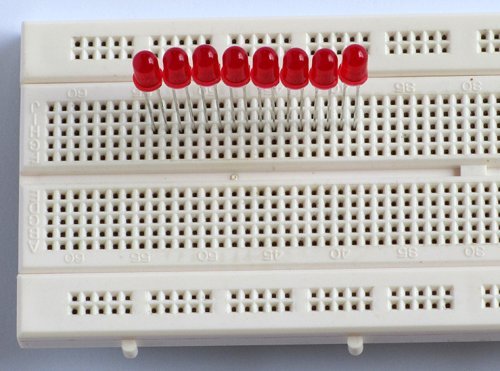
Place the LEDs next to each other in the breadboard so that the anode (longer lead) is at the left and the cathode is on the right.
Insert the 470 ohm resistors connecting one lead to the LED’s cathode and the other to the top rail.
Join the anodes of the LEDs to pins 2 to 9 of the Arduino from left to right using single-core wire. Join the top rail to one of the GND pins of the Arduino.
For more detail: Arduino Knight Rider
- What is the primary goal of this tutorial?
The goal is to interface eight LEDs to an Arduino Uno board to create a Knight rider display. - Can different colored LEDs be used for this project?
Yes, other colored and sized LEDs like 3mm green LEDs could also be used. - Which Arduino pins are used for the LED connections?
The anodes of the LEDs are joined to pins 2 to 9 of the Arduino. - How should the LEDs be placed on the breadboard?
Place the LEDs next to each other so that the anode is at the left and the cathode is on the right. - What is the role of the 470 ohm resistors in this circuit?
The resistors connect one lead to the LED's cathode and the other to the top rail. - Where does the top rail connect in the circuit diagram?
The top rail is joined to one of the GND pins of the Arduino. - Is it difficult to set up eight LEDs compared to one?
No, it is not complicated and is just like interfacing a single LED but eight times over. - What prerequisite knowledge is required before attempting this tutorial?
You must have completed tutorial 3 and its prerequisites before attempting this tutorial.
