
Summary of Boost Converter Intro with Arduino
This article explains building a simple boost converter (50–200+ V) for high-voltage projects like Nixie tubes or strobes, covering basic theory, key inductor equations, Arduino-based control (ADC required), and on/off switching behavior. It warns about efficiency loss at high step-up ratios and recommends dedicated ICs for precision or high power.
Parts used in the Boost Converter project:
- Inductor (value depends on design)
- Switching device (transistor or MOSFET)
- Diode (fast/recovery suited for high voltage)
- Output capacitor (C3 in article)
- Input voltage source (Vin, e.g., 12 V)
- Microcontroller with ADC (Arduino example)
- Gate/base drive components (resistors, drivers as needed)
- Feedback/voltage sensing components (voltage divider for ADC)
- PCB or prototyping board and wiring
- Protective components (fuses, bleeder resistors as needed)
Let’s say that you’re trying to drive a few Nixie clock tubes, or you want to make a strobe light. A variable high voltage DC power supply from 50-200+ volts may be required. Transformers are terrific, but difficult to find the right one and a pain to wind. Why not use a boost converter? They’re easy and don’t necessarily require a guru for basic operation. This guide is meant for the individual who wants to build a simple boost converter, and may need refreshing on the theory. It will also help determine what parts will be required.
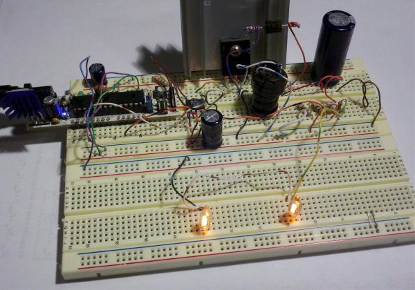 Is this guide right for you?
Basic inductor and boost converter equations. D is the duty (0 fully off, 1 fully on)
Boost converters typically get less efficient as they increase voltage out/voltage in ratio. If 100+ volts are required from a 12v source, the load will need to be a fairly high impedance. Don’t expect to run a 60watt light bulb from this boost converter! If precision is required, you may want a dedicated boost converter IC which will do the job better. This guide is intended for educational purposes.
Microcontroller:
I’m going to be using, oh you guessed it — an Arduino for this example! As usual any micro controller will do (3.3v or 5v), but this project requires analog voltage reading. If your favorite micro controller doesn’t have an ADC (Analog to Digital Converter), buy one or you can make your own!
Theory:
Boost converters work by taking advantage of a fundamental property of inductors: inductors use stored energy to maintain current. The key is that the inductor will vary voltage to maintain whatever current was present before the system (circuit) changed. Once the power supply is removed from a charged inductor, it may be easier to think of the inductor as an electromotive force rather than a passive component. Refer to the images to see it a bit more illustrated. Some of the key inductor equations are also listed.
Basic overview. Original image from Wikipedia.
On state – Current can flow through the closed switch. There is a potential difference across the inductor. The fundamental property of inductors tells us that the inductor resists change in current. Initially the inductor current is near zero when the switch closes, but current will ramp up quickly as the inductor charges till the circuit goes into the Off state.
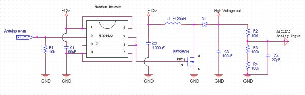 Off state – Current no longer flows through the switch. The inductor tries to maintain current, and it acts as a current source which means that voltage can sway, in this case it flips polarity due to discharge. The inductor voltage will immediately jump up to the voltage of C3 and maintain original current till the potential energy of the inductor is transferred to the capacitor. As the capacitor charges, the inductor will continue to jump up the the capacitor’s voltage, even if it’s much greater than Vin.
For more detail: Boost Converter Intro with Arduino
- Is this guide suitable for making 100+ volt supplies from 12 V?
Yes; the guide targets building a simple boost converter capable of 50–200+ volts from sources like 12 V. - Can I use any microcontroller for this project?
Any microcontroller with an ADC will work; the article uses an Arduino as an example. - Will the boost converter be efficient at high voltage ratios?
No; boost converters typically get less efficient as output voltage increases relative to input. - Can I power a 60 watt light bulb with this boost converter?
No; the article warns not to expect to run a 60 watt light bulb from this boost converter. - Do I need a dedicated boost converter IC for precision?
Yes; if precision is required, a dedicated boost converter IC is recommended as it will perform better. - What fundamental property makes the boost converter work?
Inductors store energy and resist changes in current; when the switch opens the inductor’s voltage can rise and transfer energy to the output capacitor. - What happens during the On state of the boost converter?
With the switch closed, current ramps up through the inductor as it charges while connected to Vin. - What happens during the Off state of the boost converter?
When the switch opens, the inductor flips polarity and drives current into the output capacitor, raising its voltage above Vin.
