
Summary of Designing and Building a 2m Low Pass Filter
Summary: I designed and built a 5-pole Chebyshev T low-pass filter for 2m VHF use to attenuate out-of-band emissions from DRA818V and other projects. I chose a 150 MHz cutoff (later noting 162 MHz would be better), used ARRL Handbook normalized coefficients for a 0.1 dB ripple, scaled them for 50 ohms and the target frequency, converted inductances to coil turns and capacitors to nearest values, and then assembled the filter.
Parts used in the 2m Low Pass Filter:
- Chebyshev 5-pole filter design (normalized coefficients from ARRL Handbook)
- Capacitors (values scaled from normalized coefficients to cutoff frequency)
- Inductors/coils (inductances converted to turns on chosen core)
- Core for winding inductors
- 50 ohm input/output connectors or pads
- PCB or prototyping board and wiring
- Solder and general assembly hardware
I’ve been playing with the DRA818V modules that have been making quite a stir in the amateur radio world at the moment. I haven’t gotten one on a spectrum analyzer yet, but I have reason to believe that it will require a low pass filter to be RF legal. I’ll write more about that once I get a look at it, but figured I’d first built myself a low pass filter in case I need it (if not for these modules, but some other VHF project in the future).
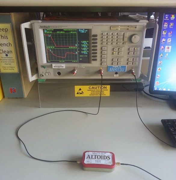
My process for building a low pass filter went as follows:
- Select the type of filter and cutoff frequency desired
- Look up normalized coefficients in the ARRL Handbook
- Divide these coefficients by the cutoff frequency
- Convert the inductances into turns on some core and capacitors into the nearest values
- Build the filter.
Since I wanted this filter for 2m, the highest frequency I’m interested in passing is 148MHz, so I selected a cutoff frequency of 150MHz. In hind-sight, this was a poor choice, since a -3dB point only 2MHz above the band caused for a lousy insertion loss. A better choice would have been 10% higher than the top of the band, so 148MHz * 1.10 = 162MHz
I decided to build a 5 pole T configuration Chebyshev filter with 0.1dB of ripple. Looking this filter up in a random copy of the ARRL Handbook (1981, but any recent one will do), it gives the component values needed for a 50 ohm filter at 1MHz. I’m also building this for 50 ohms, so all I need to convert is the frequency by dividing by 162MHz.
For more detail: Designing and Building a 2m Low Pass Filter
- How did you choose the filter cutoff frequency?
I initially chose 150 MHz to pass the 2m band up to 148 MHz but later noted 162 MHz (10% above the band) would be a better choice. - What filter topology and ripple did you use?
A 5-pole T configuration Chebyshev filter with 0.1 dB ripple. - Where did you get the normalized coefficients?
From the ARRL Handbook (example cited: 1981 edition). - How were the normalized values scaled to the target frequency?
By dividing the normalized coefficients by the chosen cutoff frequency (scaled for 50 ohms). - How did you realize inductors and capacitors physically?
Inductances were converted to coil turns on a core and capacitors were selected as the nearest standard values. - Why might 150 MHz have been a poor choice?
Because the -3 dB cutoff only 2 MHz above the band caused noticeable insertion loss; a cutoff about 10% higher would be preferable. - For what impedance was the filter designed?
50 ohms. - Is the filter intended specifically for the DRA818V module?
It was built in case the DRA818V requires a low-pass filter, but also for general future VHF projects.
