Summary of Arduino Lesson 13. DC Motors
The article explains that small DC motors draw too much power for direct Arduino connection, risking damage. A PN2222 transistor acts as a switch to control the motor using minimal current from an Arduino pin. Current flows from Collector to Emitter when triggered by a small Base current from the microcontroller.
Parts used in the DC Motor Control Project:
- Small DC motor
- Arduino digital output
- PN2222 transistor
The small DC motor, is likely to use more power than an Arduino digital output can handle directly. If we tried to connect the motor straight to an Arduino pin, there is a good chance that it could damage the Arduino.
A small transistor like the PN2222 can be used as a switch that uses just a little current from the Arduino digital output to control the much bigger current of the motor.
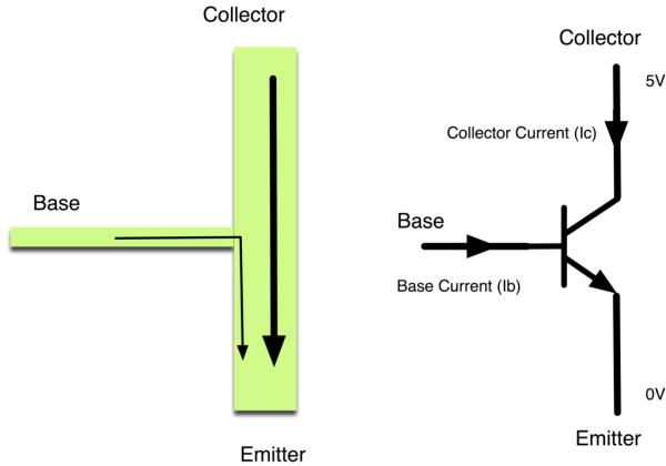
The transistor has three leads. Most of the electricity flows from the Collector to the Emitter, but this will only happen if a small amount is flowing into the Base connection. This small current is supplied by the Arduino digital output.
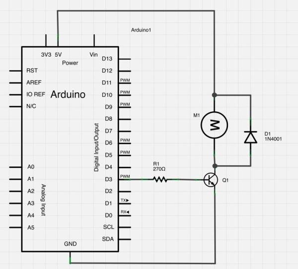
The diagram below is called a schematic diagram. Like a breadboard layout, it is a way of showing how the parts of an electronic project are connected together.
For more detail: Arduino Lesson 13. DC Motors
- Why can't I connect the motor directly?
The motor uses more power than an Arduino digital output can handle, which could damage the board. - What component controls the motor?
A small transistor like the PN2222 is used as a switch. - How does the transistor work?
It allows most electricity to flow from Collector to Emitter when a small amount flows into the Base. - Where does the base current come from?
The small current required at the Base is supplied by the Arduino digital output. - What does the diagram show?
The schematic diagram shows how the electronic project parts are connected together. - Is this similar to a breadboard layout?
Yes, it serves as a way of showing connections just like a breadboard layout.