
Summary of Autonomous Sumo Combat Robot with Pneumatic Flipper – How to
This 12-week engineering project details the design and construction of a lightweight, fully autonomous sumo combat robot capable of pushing or flipping opponents. The robot adheres to strict constraints: under 1000g, within 200x200x300mm dimensions, costing under $150 AUD excluding the microcontroller, and operating without human input. A key feature is an added pneumatic lifting system designed to flip adversaries out of the circular arena.
Parts used in the Autonomous Sumo Combat Robot:
- 47:1 Metal Gearmotor
- 10A H-bridge Dual DC Motor Driver Controller
- FingerTech Timing Pulley 26T
- FingerTech Timing Belt 276mm
- Dave Brown Lite Flite Wheels 2"
- TCRT5000 Line Tracking Sensor
- HC-SR04 Ultrasonic Sensor
- ZIPPY Flightmax Battery
- Pneumatic Cylinder Air Actuator 25mm
- Tank 100CC Air Cylinder
- Servo Operated Air Retract Actuator
- One Way Air Refill Valve
- Air retract pipe Tubing
- ShiftBrite Indicator LED
- Aluminium Sheet Chassis
- Aluminium L-Section Support
- ATMega128 Microcontroller
- 9g Servo
- Flipper arm Aluminium Sheet
- M3 cap screws
- Zip Ties
- Elastic Bands
- Connecting wires
- Solder
- Super Glue
- Pop Rivets
- Double Sided Tape
- Heat Shrink
- Power Switch
- Selection Button
- 10 wire IDE Plugs
- Microcontroller power plug
- Transistor
- Resistor
- Female Crimp Pins
- Crimp Pin Housings
- Electrical Tape
- 0.8mm Steel Wire
- 6mmX6mm square bar
- Tarzan Grip
This Sumo Bot was designed, built, programmed and tested over a 12 week period for one of my final year engineering classes. The aim was to design and build a lightweight fully autonomous sumo fighting robot for an in class Sumo Bot competition. The robot was required to push, lift or flip the opponent’s robot out of the arena.
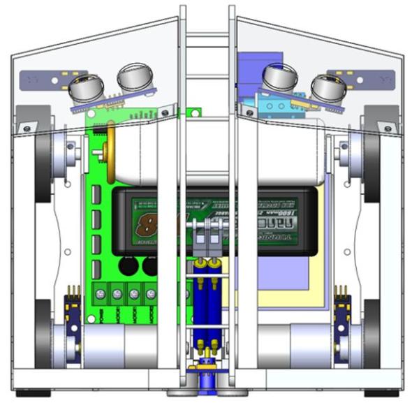
There were two physical restrictions which the sumo robot must abide by. The robot must weight no more than 1000g and is required to fit within a 200mm x 200mm x 300mm (WxLxH) measuring box. Other restrictions included the robot had to be completely autonomous with zero human interaction, must cost under $150 AUD (not including the micro-controller) and the robot must begin each round in the same orientation in which it was place in the measuring box.
We were given the option for adding a lifting/flipping system to our robots. I knew it would require a lot more work but I couldn’t resist the temptation of adding a “weapon” to the bot.
The Arena
The arena was circular with a diameter of 1.54m with a matt black surface and a 2cm wide white line around the perimeter.
Step 1: Components
This section contains a list of items required in making the Sumo Combat Robot. It has been split into two parts, the first is a list of items which were purchased and the second is a list of items which were scrounged from previous projects. All purchased items contain a link to the suppliers website.
Cost Items
2 x Motors 47:1 Metal Gearmotor 25Dx52L mm HP
1 x Motor Controller 10A H-bridge Dual DC Motor Driver Controller / High-power Strong braking
4 x Pulley Hub FingerTech Timing Pulley 26T
2 x Belt FingerTech Timing Belt 276mm (92T)
4 x Wheels Dave Brown Lite Flite Wheels 2″
4 x Line Sensors TCRT5000 Module Line Tracking Photoelectric Sensor
3 x Sonar HC-SR04 ultrasonic sensor distance measuring module
1 x Battery ZIPPY Flightmax 1300mAh 3S1P 15-25C
2 x Pneumatic Cylinder Air Actuator 25mm
1 x Pneumatic Switch Servo Operated Air Retract Actuator (Air up/Down)
1 x One way valve One Way Air Refill Valve
1 x Tubing Air retract pipe D3x1.7mm x 1m
Non-Cost Items USE
Aluminium Sheet 50cmX50cmX1mm________________________ Chassis
Aluminium L-Section _____________________________________Chassis support
Super Glue____________________________________________Sensor mounting
Tarzan Grip___________________________________________ Wheel to pulley mounting
Pop Rivets____________________________________________ Chassis assembly
Double Sided Tape______________________________________ Insulation, component mounting
Heat Shrink____________________________________________ Insulation
Connecting wires_______________________________________ Interface with components
Power Switch__________________________________________ Main power cut-off
Selection Button_________________________________________ To select between attack/evade modes
Solder_________________________________________________ Component wire connections
ATMega128 Microcontroller ________________________________Sumo robot controller
10 wire IDE Plugs________________________________________ Connect sensors to the microcontroller
Microcontroller power plug_________________________________ Deliver power to the microcontroller
Zip Ties________________________________________________ Hold pneumatics in place and tidy up electronics
Elastic Bands___________________________________________ Support pneumatic cylinder
M3 cap screws_________________________________________ Hold front wheel pins in place
Transistor______________________________________________ Switch motor controller on and off
Resistor_______________________________________________ Limit current to transistor
9g Servo_______________________________________________Control pneumatic switch
Female Crimp Pins_______________________________________ Connect microcontroller to the motor controller
Crimp Pin Housings______________________________________ Insulation over crimp pins
Electrical Tape__________________________________________ Insulation
0.8mm Steel Wire________________________________________ Link servo to the pneumatic switch
6mmX6mm square bar ____________________________________Flipper arm connection
Aluminium Sheet 20x15x3mm_______________________________Flipper arm
For more detail: Autonomous Sumo Combat Robot with Pneumatic Flipper – How to
- What are the physical weight restrictions for the robot?
The robot must weigh no more than 1000g. - How large can the robot be built?
The robot is required to fit within a 200mm x 200mm x 300mm measuring box. - Can the robot require human interaction during operation?
No, the robot must be completely autonomous with zero human interaction. - Does the robot have a budget limit?
The robot must cost under $150 AUD, not including the micro-controller. - What is the objective of the sumo bot competition?
The aim is to push, lift, or flip the opponent's robot out of the arena. - Is there a specific starting orientation required?
Yes, the robot must begin each round in the same orientation in which it was placed in the measuring box. - What type of weapon system was added to the robot?
A pneumatic lifting/flipping system was added to the robot. - What are the dimensions of the competition arena?
The arena is circular with a diameter of 1.54m and features a 2cm wide white line around the perimeter.
