
Summary of Dottie the Flip Dot Clock Using Arduino
This article details the reverse-engineering process of a flip-dot board named "Dottie." The author used an Arduino clone and multiple attempts to control 25 columns and 7 rows. Initial designs failed due to missing diodes and polarity issues, requiring H-bridges to flip dots in both directions. The final setup utilizes shift registers and transistors to manage voltage across physical lines for reliable operation.
Parts used in the Dottie Flip Dot Clock:
- Arduino Uno (Sparkfun clone)
- Shift registers
- TIP-120 transistors
- H-Bridges
- Flip-dot board
How Dottie Was Made
My trusty Arduino (it’s red, a clone from Sparkfun, and it was on sale for $10) begins this journey to reverse-engineer a flip-dot board. I figure that if I can flip one single dot, using a shift register and a couple of transistors, then all I need to do is replicate that across 25 columns and 7 rows… right?
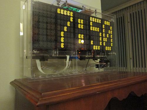
Thus began numerous attempts – I think seven in total – to figure out how exactly the board works. In this iteration, I’m trying to get a couple of shift registers to open a bank of TIP-120 transistors to send some volts on their way to the board. It gets complicated because the voltages have to go down different physical lines depending on whether you’re flipping Black-to-Yellow or Yellow-to-Black.
Turns out that 14 TIP-120s (one for each of the seven rows of dots on the board, multiplied by 2 because of the physical lines) didn’t work. I could get the flip to happen one way (sometimes) but not the other way. Potentially, my circuit design was faulty as well. Hellooo, no diodes?!
Despite these problems, the circuit is beginning to take shape. From the far left:
Arduino Uno
Shift registers to ultimately control 25 columns
H-Bridges to handle the reversing of polarity that’s needed to flip both directions
A couple more shift registers to handle the 14 rows (7 x 2) and the transistors to power each row
For more detail: Dottie the Flip Dot Clock Using Arduino
- What was the initial goal of the project?
The goal was to reverse-engineer a flip-dot board by replicating the ability to flip a single dot across 25 columns and 7 rows. - How many attempts were made to figure out how the board works?
The author made seven total attempts to determine exactly how the board functions. - Why did the initial circuit with 14 TIP-120s fail?
The circuit could only flip dots one way sometimes because it lacked diodes and had potential design faults regarding polarity. - What is needed to handle the reversing of polarity for flipping dots?
H-Bridges are required to handle the reversing of polarity needed to flip both Black-to-Yellow and Yellow-to-Black. - How many shift registers are used to control the columns?
Shift registers are used to ultimately control the 25 columns of the board. - How are the rows managed in the final circuit design?
A couple more shift registers handle the 14 rows, which consist of 7 rows multiplied by 2 for the two physical lines. - Which component powers each row in the circuit?
Transistors are used to power each row in the circuit. - What specific issue caused voltage problems in earlier iterations?
Voltages had to go down different physical lines depending on the direction of the flip, complicating the design.
