
Summary of Cylon Pumpkin Using Arduino
This article describes building a "Cylon Pumpkin" scanner using an Arduino (specifically a Boarduino) to drive 14 LEDs. The project features a scanning light effect that counts up and down, with pauses at the ends. The wiring uses a single current-limiting resistor since only one LED is active at a time. The author notes creative assembly techniques, such as splicing the circuit board for flexibility and using parallel resistors instead of specific values.
Parts used in Cylon Pumpkin:
- Arduino Boarduino
- 14 LEDs
- Current-limiting resistor (two 1k-ohm resistors in parallel)
- Proto-board
- Short wires for splicing
- 8-pin female headers
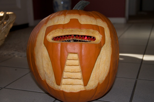
This has been done before. There are several good ways to do it: most use either a 555 timer chip and decimal counter chip, or an Arduino. Stefan and I used an Arduino (Boarduino, technically) which limited our scanner to 14 LEDs. No problem — 14 gives a nice scanning effect!
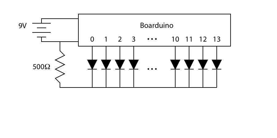
Here’s how we wired it: the numbers on the Boarduino block refer to the digital lines d0–d13.
// Cylon pumpkin driver
// Eric Ayars
// 10/24/09

#define MAXLIGHT 14

byte Wait = 50;        // Time each light is on, in ms
byte EndWait = 250;    // Time all lights are off at the ends

void setup() {
// Set all pins to output
for (byte j=0;j
pinMode(j,OUTPUT);
}
}

void loop() {

// Count up from 0 to 13, setting the light
// for each count.
for (byte j=0;j
digitalWrite(j,HIGH);
delay(Wait);
digitalWrite(j,LOW);
}

// Pause at the end
delay(EndWait);

// Count back down from 13 to 0, setting lights
// as it goes again.
for (int j=MAXLIGHT-1;j>=0;j--) {
digitalWrite(j,HIGH);
delay(Wait);
digitalWrite(j,LOW);
}

// Pause at the end
delay(EndWait);

}
Here’s Stefan with the completed “eye-bar”. We didn’t have a section of proto-board long enough to hold the entire scanner, so we split a long piece and spliced it together in the middle with short wires. This gave us the option of bending the unit in the center, which proved handy when mounting it in the pumpkin!
Rather than solder the eye-bar directly to the Boarduino pins, we soldered the wires to 8-pin female headers that then connected to the Boarduino. We labeled the headers to avoid confusion. 🙂 One side of the Boarduino has pins 0-7, and the other side has pins 8-13 and a connection to ground.
For more detail: Cylon Pumpkin Using Arduino
- How many LEDs does the scanner use?
The scanner is limited to 14 LEDs. - Does the circuit require a resistor on each LED?
No, only one current-limiting resistor is necessary because only one LED is on at a time. - What chip did the authors use instead of a 555 timer?
The authors used an Arduino (technically a Boarduino). - Why was the proto-board split and spliced?
They split the board to allow bending the unit in the center for mounting inside the pumpkin. - What resistance value was used for current limiting?
Two 1k-ohm resistors were used in parallel to act as a 500-ohm resistor. - How were the wires connected to the Boarduino?
Wires were soldered to 8-pin female headers which then connected to the Boarduino pins. - Can the code count both up and down?
Yes, the code counts up from 0 to 13 and then back down from 13 to 0. - What is the delay time when all lights are off at the ends?
The pause time when all lights are off is set to 250 ms.
