
Summary of Make your own Custom Electronic Widgets, like my Arduino LED Day/Night Widget
Summary: The author describes progressing from simple sensor-driven projects (a day/night LED using an LDR and motion sensor) to polished custom PCBs and housed multi-channel lighting controllers. They highlight iterative improvements in hardware and usability, recommend learning PCB design with Eagle CAD via online tutorials (notably rpcelectronics and Dave Jones/EEVblog), and advise starting simple, leaving solder pads when unsure, and expecting multiple board respins.
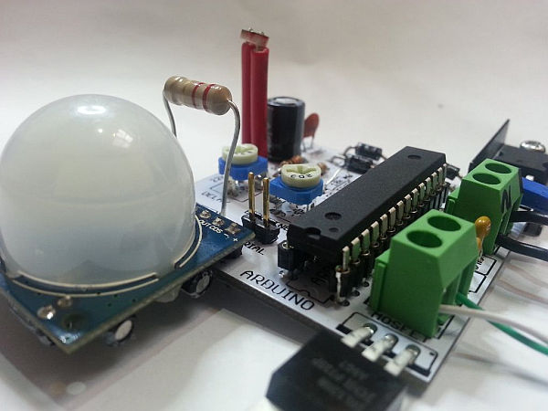
Parts used in the Arduino LED Day/Night Widget:
- Arduino (or microcontroller)
- Light dependent resistor (LDR)
- Movement sensor (motion sensor)
- LED lights
- Low voltage wiring
- Prototyping board or breadboard
- Soldered PCB (custom printed circuit board)
- Adjustable dials (potentiometers)
- Hot glue (for securing wires)
This is just a brief run down on how easy it has become to make your own circuits complete with your own PCB’s. Have you ever wanted to make something custom that suits your needs?
Of course you have!!
For me it really started when I built my first day/night light. I used a light dependant resistor to determine if it was dark and if it was to then turn on an LED light.
I then went on to add a movement sensor. From there I built a multi channel lighting controller. With very small thin low voltage wires running all over the place, hot glued in spots to the walls and floors. I can’t tell you how nice it is to have automated lighting. It seems like such a simple thing to go over and turn on a light switch, but believe me after having an automated system, If I go somewhere else to another house or hotel I realize how luxurious and satisfying it is not to have to turn the switches on and off in order as I move from room to room.
So what started out as a simple test of coding and sensors and logic, has seen me refine the design iteration by iteration. Not really in terms of capability but more in the way the parts come together and the way it is used. In terms of the hardware I have gone from breadboard, to prototyping board and soldered parts, to a fully custom printed circuit board (PCB). In the way of usability I have gone from very messy blobs of electronics laying on the floor, to an encased multi channel box, but with wires everywhere, then to a single board per light solution, with onboard adjustable dials.
Step 1: Design a circuit..
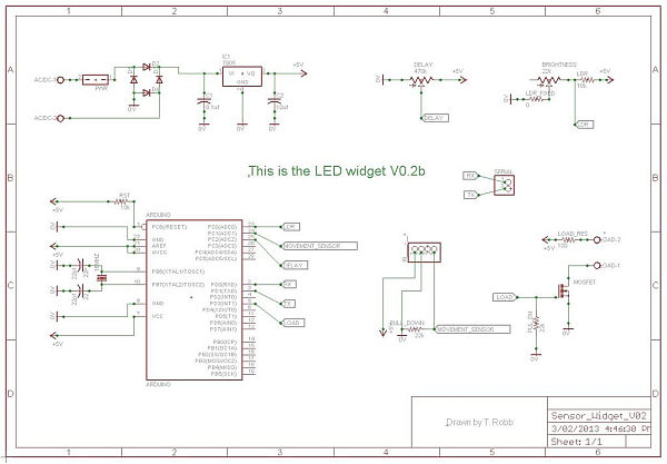
After hearing and watching Dave Jones from the http://www.eevblog.com talk about PCB layout and the possibility of getting my boards made for under $20 for 10 of them delivered to my door, I really wanted to have a go at it.
Now the first time I tried using the program without watching some tutorials I wasn’t really able to achieve much. But then I decided to use Youtube to my advantage. Yes its not just for cute cat videos.
rpcelectronics have a seriously good quick set of videos to follow along to with your own free copy of eagle cad.
Draw out your circuit, using the basic tricks shown to you in the tutorial videos. DO NOT try for anything too hard on your first attempt. You will have to respin the board a few times to add more features.
When trying to find the correct parts in the schematic library, IF IN DOUBT, just leave some correctly spaced pads there instead for you to solder to.
For more detail: Make your own Custom Electronic Widgets, like my Arduino LED Day/Night Widget
- How did the project start?
It started with a day/night light using a light dependent resistor to turn on an LED when dark. - Can motion be incorporated into the system?
Yes, the author added a movement sensor after the initial LDR-based circuit. - What progression did the hardware follow?
The hardware progressed from breadboard to prototyping board to soldered parts and finally to custom PCBs. - How did usability improve over iterations?
Usability improved from messy electronics on the floor to an encased multi-channel box and then to a single board per light with onboard adjustable dials. - What software did the author use for PCB design?
The author used Eagle CAD, following tutorial videos. - Where did the author find helpful tutorials?
The author recommends rpcelectronics tutorials on YouTube and mentions Dave Jones from EEVblog. - What advice is given for first-time PCB designers?
Start simple, follow tutorials, expect to respin boards a few times, and leave correctly spaced pads if you cannot find a library part. - Is getting custom PCBs affordable according to the article?
Yes, the author mentions the possibility of getting 10 boards made for under $20 delivered.