Summary of 14band Graphical Equalizer
This article details a DIY 14-band graphical equalizer using an MSGEQ7 chip and an ESP dev board. By employing a clever analog demultiplexing trick, the project overcomes hardware limitations to read two sets of seven audio bands simultaneously. The build involves designing a custom PCB, assembling a zigzag-patterned NeoPixel display with a 3D-printed light-diffusing mesh, and housing everything in a handmade plywood case. The software runs on Arduino IDE, visualizing sound frequencies from 60Hz to 16kHz.
Parts used in the 14 Band Graphical Equalizer:
- PCB based on MSGEQ7
- ESP dev board (NODE-MCU)
- Analog demultiplexer SN74LVC1G3157DBVR
- Two MSGEQ7 chips
- PPL oscillator (WCMCU-5351)
- Microphone breakout ADMP-401
- NeoPixel strips (WS2812B) cut into 14 pieces by 8 segments
- Fast glue or hot glue
- 3D printed mesh
- Plywood sheets
- 8x8 wooden sticks
- Sheet of paper
- Acrylic glass sheet (4mm thickness)
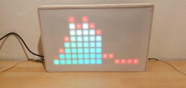
Here comes a simple Graphic Equalizer showing 14 audio bands from 60Hz up to 16kHz. It consist of a PCB based on MSGEQ7 and ESP dev board. Since a MSGEQ7 chip recognizes 7 bands only and an ESP dev board gives us a chance to read a single analog input only, there was a trick used to make it working for 2×7 bands at the same time.
I am sure this trick could be used as an inspiration for another projects as well, the same way as the project could be extended to show different animations or further modified to a stereo input instances relative simply.
Step 1: PCB and Display
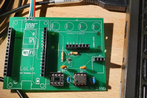
A PCB was designed based on a circuit above and the final gerber files for production of a PCB can be found here https://github.com/radimkeseg/RKG_14_BAND/tree/mas… .
It is important to mention there is an analog demultiplexer SN74LVC1G3157DBVR which was selected however its soldering is not that simple due to SOT-23 package which was too small. (I would probably use another one later for this hobby projects). Anyway this demultiplexer does the first trick with a single analog input provided by used ESP module. The way how it reads both inputs is achieved by swapping 2 used MSGEQ7 chips regularly in every reading takt to read one and then the other one. Also by using the PPL oscillator the bands of MSGEQ7 are shifted a bit, therefore it covers the 14 different bands instead of 7 bands twice the same.
The list of elements used in the PCB can be found here: https://github.com/radimkeseg/RKG_14_BAND/blob/mas…
Used breakouts ADMP-401 (microphone), WCMCU-5351 (PPL oscillator), NODE-MCU (ESP devboard).
There is also necessary to complete the “display” which is composed by NEOPIXEL (WS2812B) strips cut to 14 pieces by 8 segments. As seen in the picture above, they are soldered together the way they create a single zigzag line.
First element goes up, soldered together with second elements which goes down, and the third one again up, next down, till the end. Be careful don’t make a mistake, the software which is supporting this kind of NEOPIXEL organization. If soldered differently, the code would need to be adjusted accordingly.
Step 2:
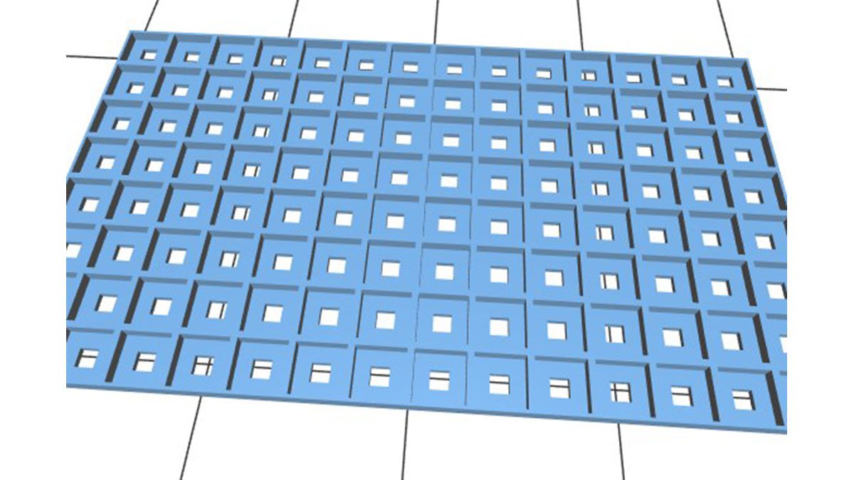
Once the NEOPIXEL display is completed, there is necessary to print a mesh that makes the end effect of a light pixel glowing as a small square.
Place the NEOPIXEL stripe into all prepared holes and fix with a fast glue or a hot glue. BTW the 3D model and gcode for 3D printing is designed for stripes that contain 60 pixels per meter. If any other clearance used the model needs to be adjusted.
The 3D model and gcode for 3D printing can be found here https://github.com/radimkeseg/RKG_14_BAND/tree/mas…
Step 3: Wooden Box
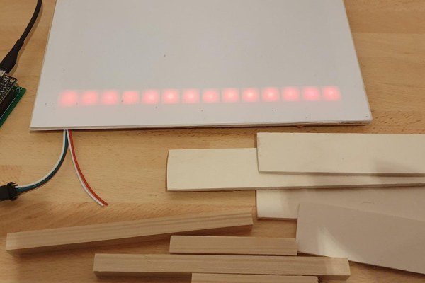
The box can be designed several ways. 3D printed or made of concrete or what ever option you could imagine and carry out. I have decided to use a simple plywood sheet and cut the proper sizes using modeler’s knife and glue them together.
To make it a bit more robust I have placed small 8×8 wooden sticks into corners.
Then I have placed the prepared display and the PCB in as shown in the picture above and fixed by a hot glue.
At the end I used a sheet of paper and placed that on top of the display and covered by a acrylic glass sheet of 4mm thickness.
The paper causes the light being dissolved and filling the full square in the printed mesh.
Step 4: Software Upload
Last step is to upload software for graphical equalizer which can be found here https://github.com/radimkeseg/RKG_14_BAND
Easiest way is to upload to Arduino IDE, import the files and then compile and upload into the ESP dev board.
Once uploaded the graphical equalizer starts working immediately listening to sound by a small microphone module.
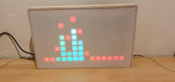
The final result can then work like this for instance.
Source: 14band Graphical Equalizer
- How does the project read 14 audio bands with only one analog input?
The design uses an analog demultiplexer to swap between two MSGEQ7 chips regularly in every reading takt. - What is the frequency range covered by this equalizer?
The device displays 14 audio bands ranging from 60Hz up to 16kHz. - How are the NeoPixel strips arranged for the display?
The strips are soldered together to create a single zigzag line where elements alternate going up and down. - What material is recommended for the diffuser on top of the display?
A sheet of paper is placed over the display to dissolve the light before covering it with acrylic glass. - Can the project be modified for stereo input?
Yes, the article states the project can be simply modified to support stereo input instances. - Which software environment is used to upload the code?
The software is uploaded using the Arduino IDE by importing files, compiling, and uploading to the ESP dev board. - What package type caused difficulty during the demultiplexer soldering process?
The SOT-23 package of the SN74LVC1G3157DBVR was noted as being too small and difficult to solder. - How should the 3D printed mesh model be adjusted if using different pixel density?
If using stripes with a clearance other than 60 pixels per meter, the 3D model needs to be adjusted accordingly.